

Topology optimization is an optimization technique that can divide the simulation domain into areas to be either kept or removed. The optimization uses an approximate representation of the physics in the areas to be removed, so you should remove these areas from the geometry and perform a new simulation to verify the optimization results. With the COMSOL Multiphysics® software, you can create geometries from topology optimization results plots for further analysis and easily export them to CAD software.
This post was originally published in 2017. It has since been updated to include more information about using the Filter dataset.
Using Topology Optimization Results in the Design Workflow
Topology optimization is a useful capability because it can help us find designs that we would not have reasonably been able to think of ourselves. When developing a design, however, this is only the first step. It may not be reasonable or possible to construct a particular design found through topology optimization, either because the design is too costly to produce or it is simply not possible to manufacture.
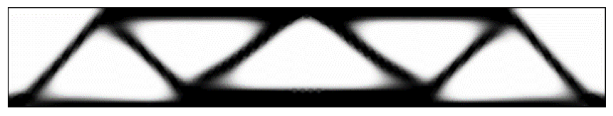
Topology optimization results for an MBB beam.
To address these concerns, we can come up with new designs that are based on the results of topology optimization, and then carry out further simulation analyses on them. But how do we do this? We either need a geometry that we can mesh, or we need an imported mesh representing the topology optimization results. As it turns out, COMSOL Multiphysics makes it simple to create both of these from 2D and 3D simulations, which you can continue to work with directly in COMSOL Multiphysics or export to a wide range of CAD software platforms. We will start by looking at how to create a geometry and will then move on to discuss how we can skip the step of creating a geometry by importing and modifying a mesh to prepare it for simulations.
How to Generate a Geometry of Topology Optimization Results in COMSOL Multiphysics®
The steps to generate a geometry of topology optimization results using a Filter dataset is the same for 2D and 3D geometries as of COMSOL Multiphysics version 5.5. However, there are some additional steps for 2D geometries. Let’s use the Minimizing the Flow Velocity in a Microchannel tutorial to demonstrate this process. In addition to the original tutorial, we will also show how added domain and boundary Selections are imported and can be reused while running verification studies on the newly created geometry. An MPH-file with the added selections and verification study can be downloaded via a link at the end of this blog post.
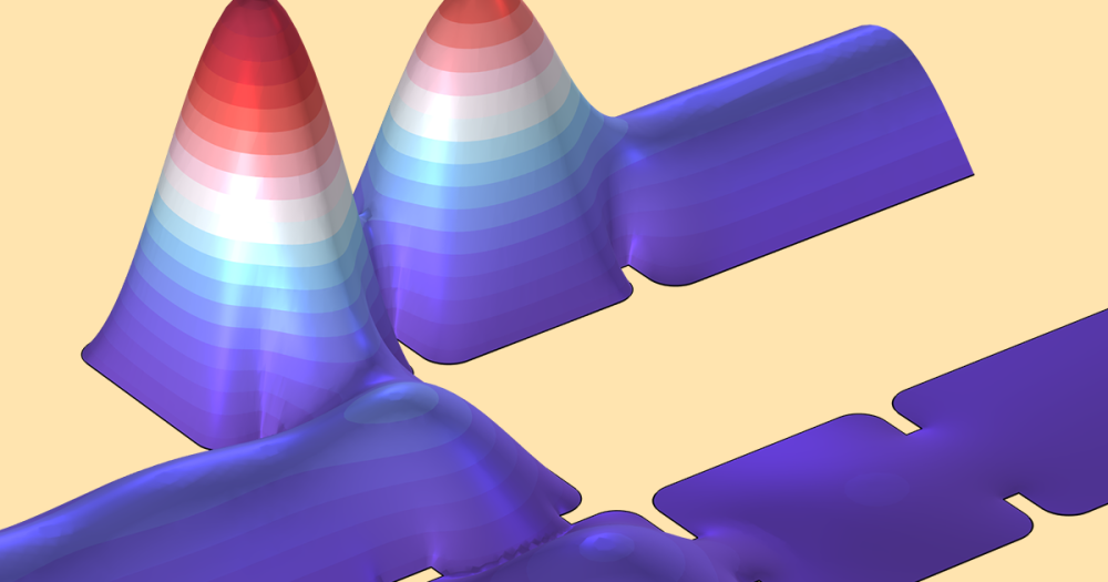
The goal of the tutorial is to find an optimal distribution of a porous filling material to minimize the horizontal flow velocity in the center of a microchannel.
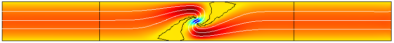
The horizontal velocity (surface plot) and velocity field (streamlines) after optimization. The black contours represent the filling material.
In the results plot above, the black contour is where the design variable, \gamma, equals 0.5. This indicates the border between the open channel and filling material, which is the result that we would like to incorporate into the geometry. In other applications, the expression and exact level to plot may differ, but the principle is the same: to find a contour that describes the limit between the solid and nonsolid materials (typically a fluid of some kind).
Adding and Setting Up a Filter Dataset
To create a geometry out of this result, we will use a Filter dataset. For a 3D topology optimization study, such a dataset is set up automatically with the default plots. However, for 2D, this needs to be set up manually by adding a Filter dataset from the More Datasets menu on the Results ribbon.
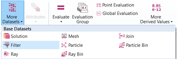
The More Datasets menu on the Results ribbon presents one way of adding a Filter dataset.
In the Settings window for the Filter node, enter dtopo1.theta as your Expression and set Lower level: 0.5. Clicking the Plot button gives a visualization of the regions represented by this level.

The image shows the settings for the Filter dataset as well as the plot of the region defined by the dataset.
Creating a Mesh Part Based on the Filter Dataset
The next step in the process is to right-click the Filter node in the Model Builder tree and select Create Mesh Part from the menu.
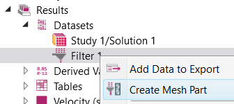
Use the Create Mesh Part attribute as a first step in the process to create a geometry out of the topology optimization result.
This action sets up a Mesh Part with a mesh based on the visualization of the Filter dataset. As seen in the image below, there is a check box, Import of selections, in the Settings window of the Mesh Part > Import operation. The imported selections are also listed below the import settings, categorized based on entity level. In this example, the selections on the original geometry were coordinate-based selections used to define the material and physics settings of the topology optimization study.

The Settings window of the Import node for the Mesh Part. The selected setting Import selections gives the list of selections in the bottom of the Settings window. As seen in the Model Builder tree, selections were defined both in the Geometry sequence as well as under Definitions in Component 1.
The mesh Import operation supports import of any type of model selection. The most common types of selections are the ones added under Definitions, the ones added in the sequence of Geometry operations, as well as selections created during LiveLink™ synchronization and mesh import. As of COMSOL Multiphysics version 5.5, selections can also be automatically created during CAD import based on material, color, objects (bodies), and layers in the CAD file.
After the mesh has been imported, it can be modified using, for example, Partition Entities operations to create more entities, or Join Entities to result in fewer entities. It is also possible to use the Adapt operation to modify the mesh before creating a geometry, as is shown in the tutorial Exporting and Importing a Topology-Optimized Hook. For a 3D mesh, we can directly export the mesh to a format that is compatible with COMSOL Multiphysics and CAD software, and can even be used directly for 3D printing. The supported file formats for use in external software are the STL, 3MF, and PLY formats, which are common file formats for 3D scans and 3D printing.
How to Create a Geometry and Reuse the Imported Selections
When satisfied with the mesh, right-click the Mesh Part node and select Create Geometry from Mesh from the menu. This sets up a new component in the Model Builder with an Import node in the sequence of geometry operations. We discussed the process and import settings involved in the 3D case in greater detail in a previous blog post.
The imported selections can now be used to set up the material and physics settings in a verification study, as shown in the image below.

Geometry created from the topology optimization result. The Inlet boundary condition is set up with one of the boundary selections imported through the Mesh Part.
You can also make a copy of your MPH-file, clear the sequence of geometry operations, add an Import operation, and point to the newly created mesh part directly. That way, you can reuse the setup of the physics by just making sure that the selections have been properly updated.
Alternative Procedure: Running a Verification Study Directly on Mesh Created from a Filter Dataset
As of COMSOL Multiphysics version 5.5, we can avoid the step of generating a geometry and work directly with a mesh created from the Filter Dataset. The operations make it possible to adapt the surface mesh in order to improve the mesh quality, create domains if needed, and build a free tetrahedral mesh — all based on the imported mesh. This procedure is done as follows, using the solved version of the tutorial Exporting and Importing a Topology-Optimized Hook as a starting point:
Add a new 3D Component and go to Mesh 4 in Component 3. Note that it is also possible to go to any of the meshes in the two existing components and select Delete Sequence to reuse the physics already set up there. In the component you chose, add a mesh Import operation and set Source: Filter dataset and Dataset: Filter 1, as shown in the screenshot below. The Import selections check box is selected by default to make it easier to set up the physics of the verification study, which we discussed in the previous section. These selections are listed under the Domain Selections and Boundary Selections, respectively. For this use, it is recommended to only import the boundary mesh elements and create the domain mesh separately (see steps below) as this gives better quality meshes. This import results in the mesh and imported selections shown in the image below.

Mesh created from a Filter dataset defining the topology optimization result. The selections from the original component are transferred to the new mesh.
An imported mesh from a Filter dataset is based on the mesh used for visualizing plots and is therefore not ideal for simulations. To improve the quality of the mesh, add an Adapt operation, here with settings Solution: None, Type of expression: Absolute Size, and Size expression: meshsz/2, where meshsz is an already-defined parameter used to define the mesh size used in the topology optimization study.
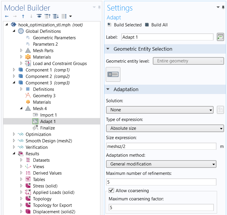
Settings used to adapt the surface mesh to the size defined by the expression meshsz/2.
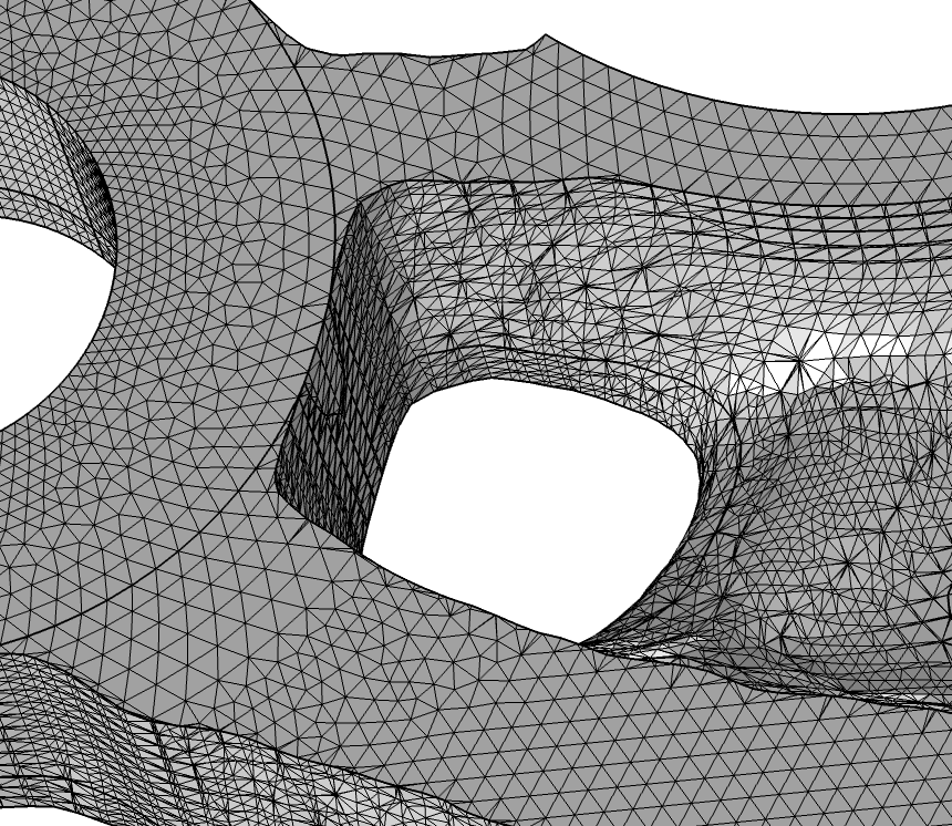
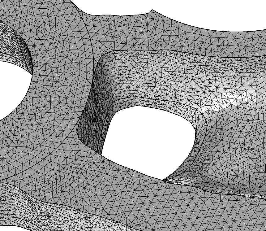
The surface mesh before (left) and after (right) building the Adapt operation.
The entity information is also transferred from the Filter dataset, so there are domains, even though we only transferred the surface mesh. In case you import a surface mesh from file, you also need to add a Create Domains operation before going on to the next step, otherwise there will be no domains to mesh. Lastly, we add a Free Tetrahedral operation to build the domain mesh. Make sure to set an appropriate size setting in the Size operation below the Free Tetrahedral node. Here, we set the predefined mesh size to Finer and build the mesh.
You are now ready to set up the physics in your verification study.
Comparison of the Two Procedures
We have looked into the possibility of creating a geometry or a mesh based on a Filter dataset. So, is there anything to consider when choosing between the two procedures?
By creating a geometry, you ensure that nonplanar faces are represented with curved elements, while a mesh created directly from a Filter dataset can only use a piecewise linear representation of the boundaries. If the physics you are solving is highly dependent on a smooth representation of curved boundaries, you might want to consider creating a geometry. Also, by creating a geometry, you can remesh the boundaries freely, while you are restricted to adapting the boundary mesh when solving directly on the mesh created from the topology optimization results.
On the other hand, creating a geometry is more time consuming and consumes more memory than working with a mesh only. Also, depending on the shape of the topology optimization result, it might not be possible to create a geometry based on the result. A too-coarse mesh representing small or narrow regions is a typical situation where you might want to consider solving directly on an imported mesh.
Exporting 2D Geometries to CAD Software
The DXF format is a 2D format that most CAD software platforms can read. DXF also describes the higher-order polygons between the points, so it usually gives a better representation than exporting only the points.
To export the optimized topology from this geometry to a DXF file, we can follow the steps below. Please note that there is an optional step for if you want to exclude domains in your DXF file.
- Add a Union from the Booleans and Partitions menu on the Geometry toolbar
- Include all of the objects
- Use a Delete Entities feature to remove any unwanted domain (optional)
- Click the Export button on the Geometry toolbar to write to the DXF format for a 2D geometry
How to Export 3D Plot Data in the STL, PLY, and 3MF Formats
After performing a topology optimization in 3D, we usually view the resulting shape by creating a plot of the design variable; for example, an isosurface plot. In COMSOL Multiphysics, it is possible to export STL, PLY, and 3MF files from the following plot features:
- Volume
- Isosurface
- Surface
- Slice
- Multislice
- Radiation Pattern
The software also supports adding a Deformation node on the plot feature, in case we want to export a deformed plot.
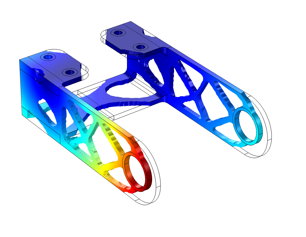
Topology optimization results of a bracket. The color in the Volume plot denotes the total displacement. This plot data can be exported directly on several formats for further use in CAD software and for 3D printing.
Exporting the data into an appropriate file format is straightforward and is also shown in the tutorial Bracket — Topology Optimization. We right-click the Plot Feature node and select Add Plot Data to Export. In the Settings window of the resulting Plot node, we then select STL Binary File (*.stl), STL Text File (*.stl), PLY binary file (*.ply), PLY text file (*.ply), or 3MF file (*.3mf) from the File type drop-down list.
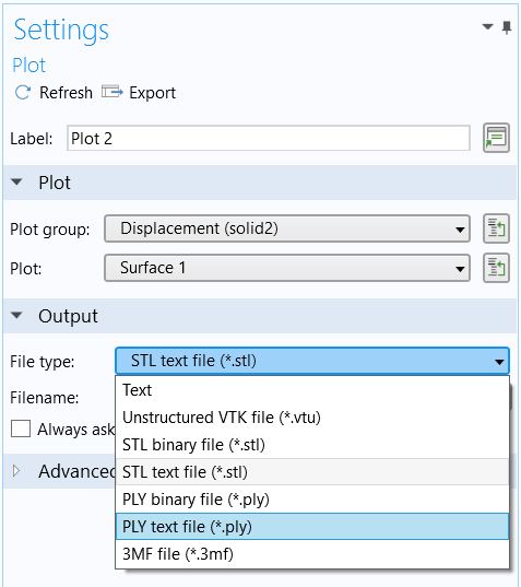
Plot data export settings. The supported output file formats for use in CAD software and 3D printing are STL, PLY, and 3MF.
The 3MF and PLY files will also contain color data for all of the mesh nodes. The exported file is readily readable by most CAD software and 3D printing platforms.
Summary on Creating Geometries from Topology Optimization Results
If you want to compare actual CAD drawings with your optimized results, you need to export the data in a format that can be imported into the CAD software you are using. The DXF format (for 2D) and the STL, 3MF, and PLY formats (for 3D) are widely used formats and should be possible to import in many software platforms.
In this blog post, we have discussed the steps needed to export topology optimization results in the DXF, STL, 3MF, and PLY formats. This will enable you to more efficiently analyze your model geometries within COMSOL Multiphysics and CAD software.
Learn more about how COMSOL Multiphysics can fit your CAD and topology optimization needs by clicking the button below:
Further Resources
Learn more about topology optimization and exporting geometries on the COMSOL Blog:


Comments (6)
Trevor Munroe
February 1, 2017For Topology Optimization of the 3-D bridge, would the Level Set Method produce more well defined or delineated boundaries?
Hanna Gothäll
February 22, 2017Hi Trevor, Thanks for your comment. It would, in principle, be possible to use the Level-Set method to get smoother boundaries, but this is not tested. In case you come up with some results, please feel free to leave a follow-up comment.
Ed Bervoets
February 22, 2017Hi Hanna, thanks for the good explanation.
I tried to export the optimised geometry to STL as described above on a volume node with filter rho_design > 0.1. I get the correct optimised geometry alright in my plot window, but if I export it to STL, the whole design domain gets stored (which is just a solid block) and not the optimised geometry.
Did I miss something somewhere? Maybe you could explain step by step how it is done and post the optimised STL?
Thanks in advance!
Hanna Gothäll
February 23, 2017Hi Ed, I’m glad that the blog post comes in handy! Please send the mph file to COMSOL Support so that we can assist you with your particular application.
Kyaw Ye Ko
September 9, 2020How do you solve topology optimization of heat transfer? What is need to do? I not found this problem in this Comsol website and other.
Hanna Gothäll
September 11, 2020 COMSOL EmployeeDear Kyaw Ye Ko, To be able to answer your request in greater detail, we kindly ask you to send your question to COMSOL Support: support@comsol.com or through the the form on the website https://www.comsol.com/support/case/ .