Modelling of a Thermal Time-of-Flight Sensor for Low Rate Open Channel Flow
Water transport in the public sewer system is often based on open channel flow, e.g. in a DN100 drainage pipe. Especially for low flow rates of less than 10 mL/s and with water levels of less than 4 mm, flow sensors are hardly available. In order to enable the measuring of very low flows, a novel measurement method was developed. The principle of TTOF (thermal time-of-flight) measurement is used. The heating element and the temperature sensors, implemented as NTC (negative temperature coefficient), is integrated into the bottom area of the channel wall. The sensors are located downstream and measure the time difference of the passing heat cloud induced by the heat element. Explorative studies indicate that there are interdependencies between the fluid dynamics and the thermal effects, such as vortexes caused by wrong-dimensioned pulses in terms of amplitude and width. In addition, the spatial dimensions of the heat and sensing elements have flow velocity dependent optima in terms of the measured temperature pulse amplitude.
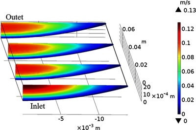
TTOF-simulations for fully filled pipe flow are reported in [1]. In this work low rate open channel flow is considered. The COMSOL Multiphysics® model setup is based on the Nonisothermal Laminar Flow interface in 3D. Regarding Laminar Flow, the following boundary conditions (BCs) are used: Wall set to Slip for the fluid surface, Symmetry for numerical efficiency, Inlet set to a pre-calculated velocity-profile and Outlet set to Pressure. Regarding Heat Transfer in Fluids a Boundary Heat Source is inserted. A Rectangle function is utilized to switch the heating element for transient simulations.
To optimize the transient simulation time, the geometry and thereby the degrees of freedom should be minimized. Therefore, only half of the cross-section (symmetry BC) and a minimized channel length resulting from the positions of the heater at the inlet (begin) and the last downstream NTC (end) are taken into account. However, use of this geometry requires a well-established flow profile at the inlet. To calculate the profile the following strategy is used: A Component 1 is setup with Laminar Flow, only, and with a channel length much longer than the minimized one. Furthermore, the Inlet BC is set to fully developed flow, here. The resulting outflow profile obtained from a first stationary study step is transferred to the inlet of the final geometry in Component 2 with a Linear Extrusion operator. A second stationary study step for Nonisothermal Laminar Flow in Component 2 (with minimized channel length) is used to calculate initial conditions for the transient simulation performed in a third study step.
To model the NTCs temperature signals, boundary Average Component Coupling operators are defined. To take into account the thermal inertness of the NTCs, global ODEs are added to Component 2 with parameters obtained from experimental data.
The developed model enables to validate the measurement principle, to find the maximum measurement range and to optimize the flow sensor construction parameters.
[1] Ecin, O. et all: Modelling Thermal Time-of-Flight Sensor for Flow Velocity Measurement In: Proceedings of the COMSOL® Conference 2009
Download
- Poster_Cambridge_2019_TTOF.pptx - 1MB
- Paper_Comsol2019-TTOF_V14.pdf - 1.56MB