MEMS Module Updates
For users of the MEMS Module, COMSOL Multiphysics® version 5.3a brings updated electromechanics, thermoelasticity, fluid-structure interaction, and moving mesh multiphysics couplings with improved functionality. Learn more about these MEMS Module updates below.
Electromechanics
The Electromechanics physics interface has been upgraded to a fully formed multiphysics interface. When you add the Electromechanics physics to your model, the Electrostatics and Solid Mechanics physics interfaces are added, coupled together with the Electromechanical Forces multiphysics coupling to solve the structural equations together with the equations of electrostatics. A Moving Mesh node is added to the Definitions section, with Deforming Domain and Symmetry subnodes. The new approach improves the flexibility and design options for your modeling of electromechanics.

Displacement in a biased resonator using the improved Electromechanics multiphysics interface.
Thermoelasticity
The Thermoelasticity physics interface has been upgraded to a fully formed multiphysics coupling. When you add the Thermoelasticity physics to your model, the Solid Mechanics and Heat Transfer in Solids physics interfaces are added, coupled together with the Thermal Expansion and Temperature Coupling multiphysics couplings to solve for the displacement of the structure and the temperature deviations, and the resulting heat transfer induced by the thermoelastic coupling. A Moving Mesh node is added to the Definitions section, with Deforming Domain and Symmetry subnodes. The new approach improves the flexibility and design options for your modeling of thermoelasticity.
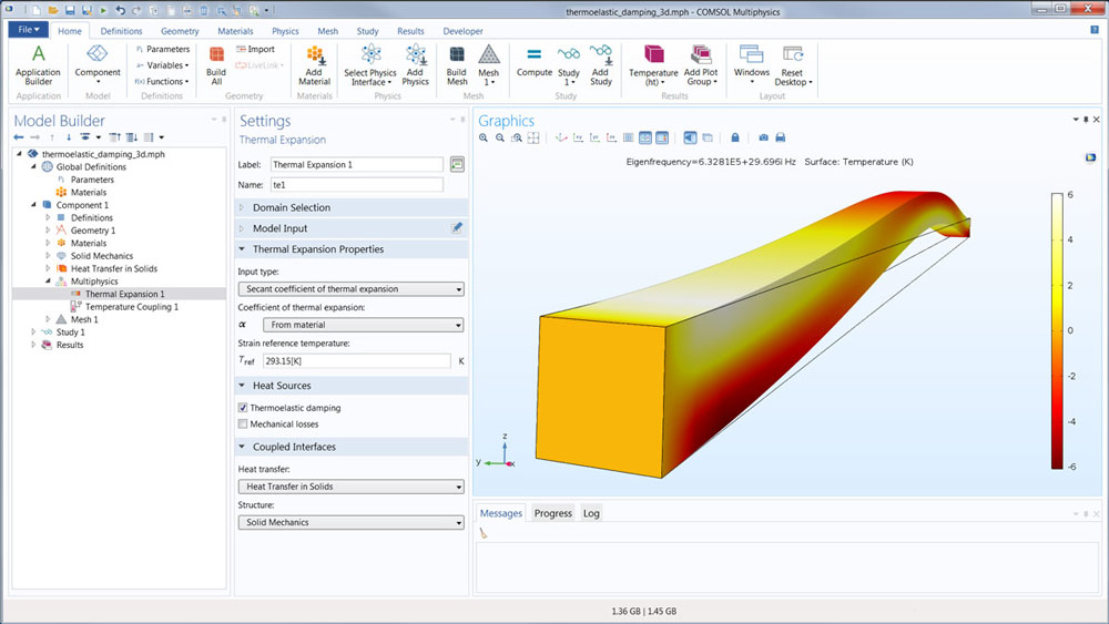 First eigenmode and temperature deviation for a 3D thermoelasticity model.
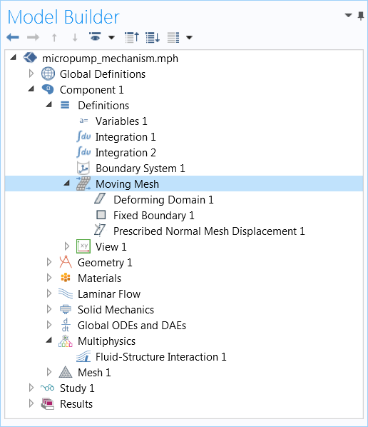
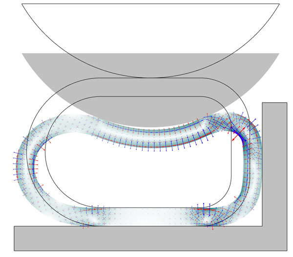
Fluid-Structure Interaction (FSI)
A new Fluid-Structure Interaction multiphysics coupling has replaced the interface used in previous versions of the COMSOL® software. The new coupling matches the modern style, with a number of single-physics interfaces and multiphysics nodes to couple them together. With this approach, all functionality in the constituent physics interfaces is available for modeling FSI. On the structural side, many additional boundary conditions and material models are now available for FSI analysis; for example, rigid domain, piezoelectric, and nonlinear elastic material models. On the fluid side, all turbulence models are now available as well as a number of new boundary conditions. After adding a Fluid-Structure Interaction interface from the Model Wizard, you will get a Solid Mechanics interface, a Laminar Flow interface, a Fluid-Structure Interaction multiphysics coupling node, and a Moving Mesh node in the Definitions section. All FSI models in the Application Libraries have been updated to include this new coupling functionality.
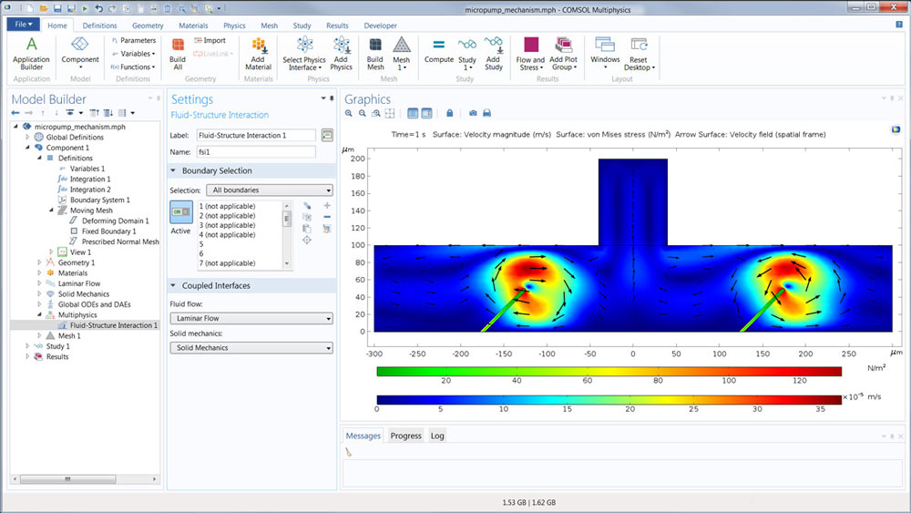
The Micropump Mechanism model has been updated to include the new Fluid-Structure Interaction multiphysics coupling.
FSI with Two-Phase or Three-Phase Flow
It is now possible for MEMS Module users who also have a CFD Module license to perform FSI simulation with two-phase or three-phase flow physics, thanks to the improved Moving Mesh machinery in the core functionality of the COMSOL Multiphysics® software (see the section below).
Generalized Moving Mesh Functionality
The Moving Mesh functionality is now available from the Moving Mesh submenu when right-clicking the Definitions node under a Component and from the Definitions toolbar.
The moving mesh features control the spatial frame in a model and may apply to all physics in a model where the domains are deforming or moving. They can be used to study both stationary states and time-dependent deformations where the geometry changes its shape due to the dynamics of the problem. For example, Deforming Domain features, added under the Moving Mesh node, can be used for fluid domain deformations in FSI or electrostatic domain deformations in MEMS. Other features can specify that parts of the model rotate such as in the case of fluid mixers or electrical motors.
The moving mesh features available under Definitions are the new default mechanism for multiphysics interfaces with moving meshes. It is used instead of the Moving Mesh (ALE) physics interface, which is still available as an alternative to the new moving mesh functionality.
Generalized Plane Strain
For 2D solid mechanics, a generalized plane strain formulation has been developed as a third option to the plane strain and plane stress approximations. The generalized plane strain approximation is intended for modeling the central part of structures that are long and have a constant cross section. For these cases, as opposed to a standard plane strain formulation, nonzero out-of-plane strains are present.

When selecting the type of 2D approximation, you can choose the Generalized plane strain formulation.
Improved Default Plots
The default plots in the structural mechanics physics interfaces have been updated to produce more informative visualizations. The Application Library tutorials have been updated accordingly. Some of the more prominent changes that you will see are as follows:
- The color table for von Mises stress plots is RainbowLight
- The color table for mode shape plots, for eigenfrequency and linear buckling studies, is AuroraBorealis
- Mode shape plots have the legend switched off to emphasize that the amplitude of a mode does not have a physical meaning
- The color table for section force plots in the Beam and Truss interfaces is Wave, with a symmetric color range
- This makes it possible to immediately distinguish between tension and compression, for example
- In contact analysis, a plot of the contact pressure is added, as either a line plot (2D) or contour plot (3D)
- The default plot for Stress Linearization now has a legend for the graphs
- The default Undeformed geometry plot, produced by the Shell interface, has new colors
- When a material model like plasticity or creep is used, a contour plot of a relevant strain quantity, like the effective plastic strain, overlays the stress plot
- Applicable for the Nonlinear Structural Materials Module and the Geomechanics Module
- In the Fatigue interface, the Traffic color table is used for predicted cycles to failure and for usage factors
- Applicable for the Fatigue Module
Improved Plots for Principal Values
The plot type Principal Stress can now be used for any kind of tensor principal values. In earlier versions of the COMSOL® software, only a single predefined stress or strain field could be selected, but now you can manually enter orientation vectors and corresponding principal values.
A new set of principal strains have been added to the results in the Solid Mechanics interface: Principal logarithmic strains. This is the logarithmic strain, or "true" strain, with orientations given in a space-fixed coordinate system, well suited for plotting on the deformed geometry in a geometrically nonlinear analysis.
Also, a new Principal Stress Line plot type has been added that is particularly useful in the Shell and Plate interfaces. Previously, the principal value plots were only available for volumes and surfaces.
 Logarithmic strains plotted on a deformed rubber seal.
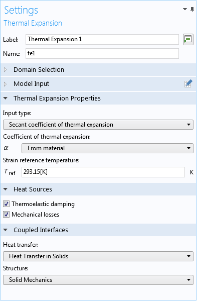
Mechanical Losses Associated to Thermal Stress
The Thermal Expansion multiphysics coupling node now automatically handles the mechanical losses due to thermal stress; the generated heat source is added to the heat transfer equation in the corresponding domains. A Mechanical losses check box is available in the new Heat Sources section of the Thermal Expansion node to control this behavior.
New Fluid-Structure Interaction Interface That Supports All Turbulence Models
A new Fluid-Structure Interaction multiphysics coupling has replaced the interface used in previous versions of the COMSOL® software. The new coupling matches the modern style, with a number of single-physics interfaces and multiphysics nodes to couple them together. With this approach, all functionality in the constituent physics interfaces is available for fluid-structure interaction (FSI) modeling. On the structural side, many additional boundary conditions and material models are now available for FSI analysis; for example, rigid domain, piezoelectric, and nonlinear elastic material models. On the fluid side, all turbulence models are now available as well as a number of new boundary conditions. After adding a Fluid-Structure Interaction interface from the Model Wizard, you will get a Solid Mechanics interface, a Laminar Flow interface, a Fluid-Structure Interaction multiphysics coupling node, and a Moving Mesh node in the Definitions section. All fluid-structure interaction models in the Application Libraries have been updated to include this new coupling functionality.
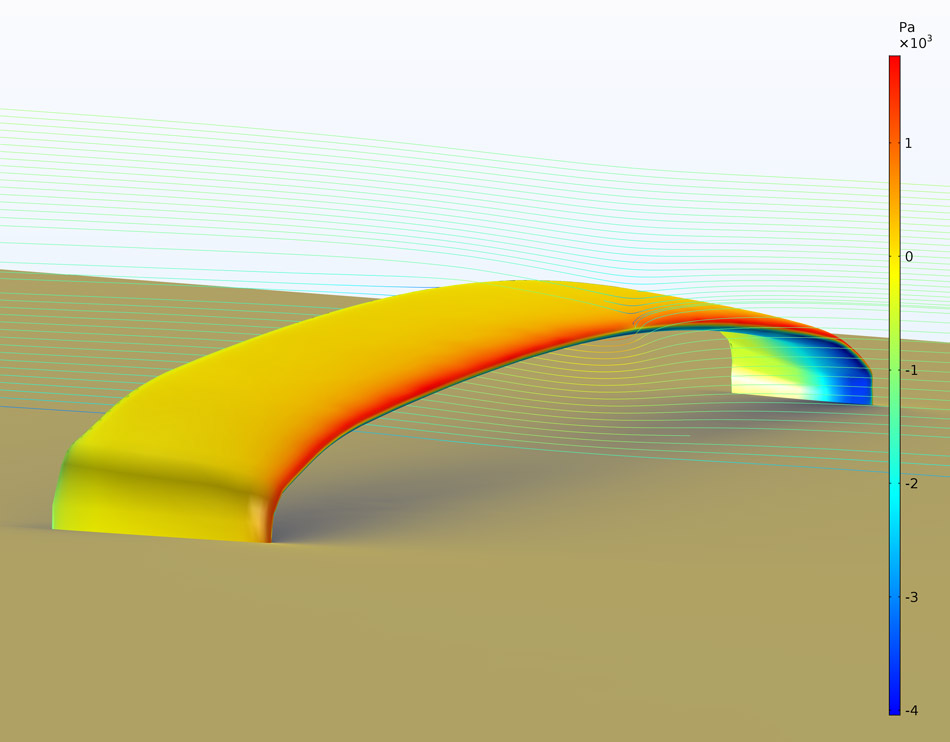 Pressure (color table) and deformation (exaggerated by a factor of 50 at the surface) of a sports car wing subjected to turbulent flow (streamlines) of 200 km/h (125 mph) in a test bench. The model is defined using one-way fluid-structure interaction in the new physics interface.