Ray Optics Module Updates
For users of the Ray Optics Module, COMSOL Multiphysics® version 5.3a brings new ray release distributions and more flexible boundary conditions. The dedicated Part Library for the Ray Optics Module has been expanded with new mirrors and lenses. Browse all of the Ray Optics Module updates in more detail below.
Grid-Based Release with Cylindrical and Hexapolar Coordinates
You can now release rays from a cylindrical or hexapolar grid of points when using the Release from Grid feature. You can control the center and orientation of the cylindrical distribution, the number of different radial positions, and the number of angles.
 Cylindrical grid-based distributions can be specified with uniform gaps between rings of grid points (left), gaps scaled to approximate uniform spatial number density (middle), or user-defined radii (right).
 From left to right: Hexapolar grids containing two, five, and ten rings of points.
Faster Release from Boundaries
Releasing rays from boundaries with uniform and density-based distributions is much faster in COMSOL Multiphysics® version 5.3a as compared to version 5.3, increasing the performance of models that use the Inlet and Illuminated Surface features.
The following table shows the performance improvements in the Solar Dish Receiver tutorial model from the Application Library. In this model, a large number of rays are released from an illuminated parabolic reflector aimed at the sun.
| Number of Rays | Solution Time(s), Version 5.3 | Solution Time(s), Version 5.3a | Speedup |
|---|---|---|---|
| 1000 | 5 | 4 | 25% |
| 2000 | 8 | 3 | 170% |
| 5000 | 16 | 5 | 220% |
| 10,000 | 41 | 6 | 7x |
| 20,000 | 53 | 9 | 6x |
| 50,000 | 130 | 19 | 7x |
| 100,000 | 244 | 36 | 7x |
Running on Intel® Xeon® CPU E5-2620 v2 at 2.10 GHz. Using 6 cores on 1 socket. Available memory: 16.33 GB.
Suppress the Release of Reflected Rays During Refraction
At the material discontinuities between different media, you can now easily control which surfaces produce reflected rays when an incident ray is refracted. By default, the incident ray is always split into reflected and refracted rays, as long as the refractive indices on either side of the boundary are different. Optionally, you can prevent the boundary from producing reflected rays or release reflected rays only when a specified logical expression is satisfied.
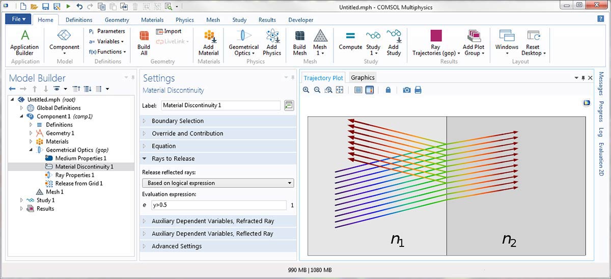
Settings window for the Material Discontinuity node in which the reflected rays are released based on the logical expression y>0.5.
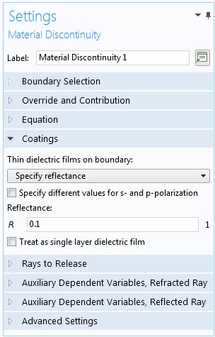
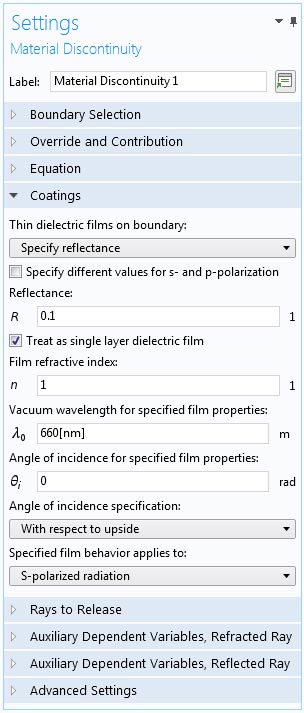
Easier Ways to Specify Reflectance and Transmittance at Boundaries
In the settings for the Material Discontinuity feature, it is now much easier to set up a boundary with user-defined reflectance or transmittance, even if you do not know the material properties of the dielectric coatings at the interface. The reflectance or transmittance is a numeric value by default, but can also be an expression or even an analytic or interpolation function.
New Options for Setting Up Diffraction Gratings
Some new options are available in COMSOL Multiphysics® version 5.3a to provide greater flexibility when setting up diffraction gratings. To specify the orientation of the grating in 3D, you can now either enter the direction of periodicity (from one unit cell to the next) or the direction of the lines in the grating. Additionally, the rays of diffraction order zero are no longer automatically controlled by the Grating feature itself. Instead, they are controlled by a Diffraction Order subnode, just like all nonzero diffraction orders. When you create a Grating node, a Diffraction Order subnode is now created by default. This way, you can omit rays of order zero if they are not important to the model.
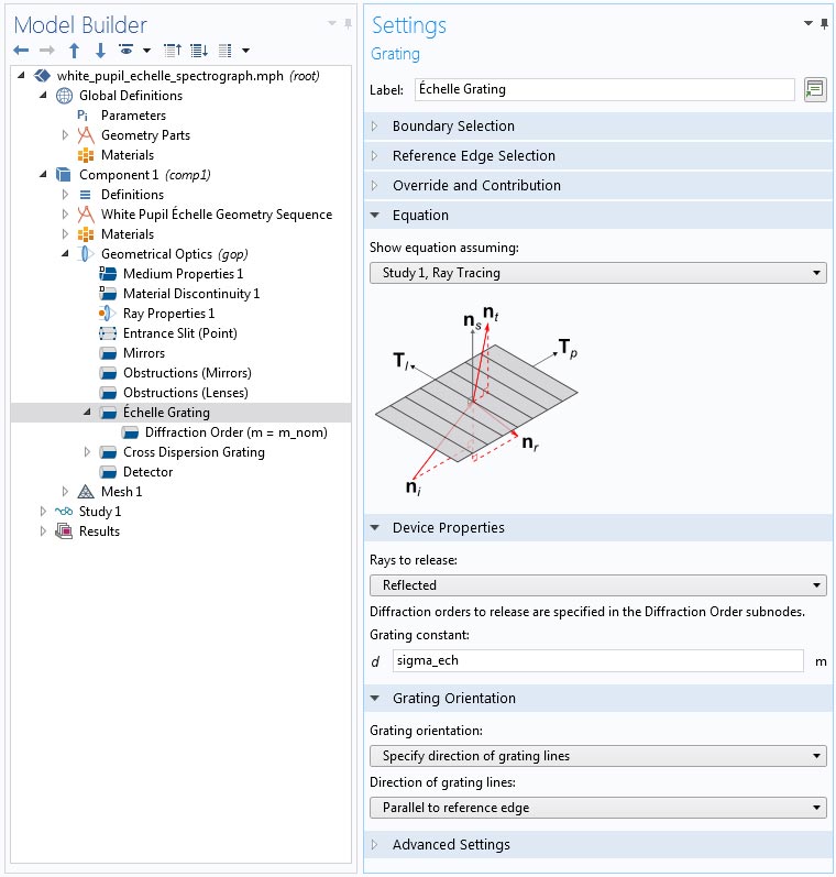
Settings window for the Grating feature, with the new Diffraction Order subnode.
Mirror Boundary Condition
A dedicated Mirror boundary condition, now available as a special case of the Wall boundary condition, always specularly reflects the incoming rays.
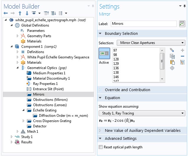
Settings window for the Mirror feature.
Study Termination Based on Number of Reflections
You can now automatically count ray reflections at boundaries. Simply select the Count reflections check box and a built-in variable will be used to store the number of times each ray is reflected at walls and material discontinuities. In addition, the Ray Tracing study step has a built-in option to automatically end the study if all active rays have been reflected at least a specified number of times. Use this option to avoid spending unnecessary time waiting for the study to terminate when each ray has already been reflected many times.
Part Library Improvements
Four new parts have been added to the dedicated Part Library for the Ray Optics Module: Spherical General Lens, Circular Planar Annulus, On Axis Conic Mirror, Off Axis Conic Mirror.
Spherical General Lens
Use the Spherical General Lens part to define lenses with two different radii of curvature on either side. This lens geometry is much more general than the built-in parts for equi-convex and plano-convex lenses, providing inputs to specify a clear aperture at either lens surface.
 Spherical General Lens in the Part Libraries.
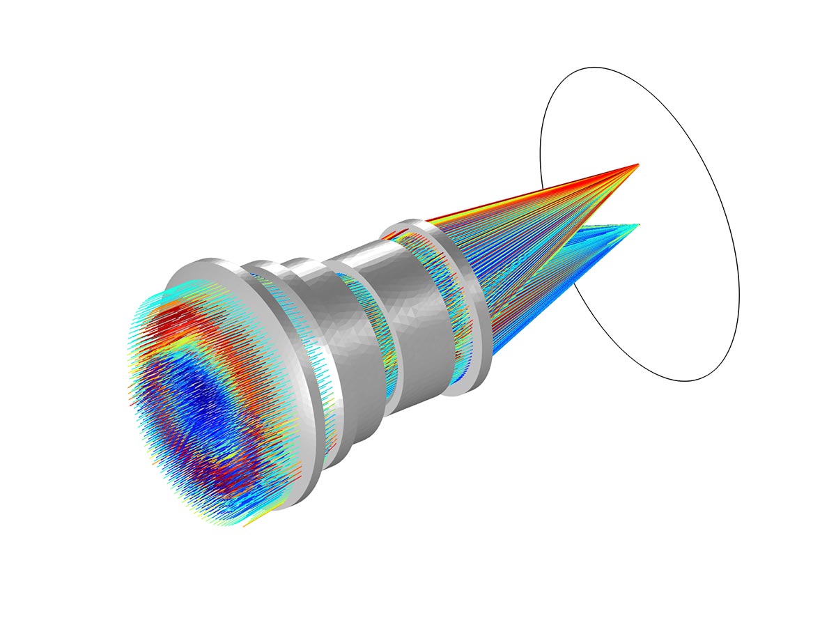
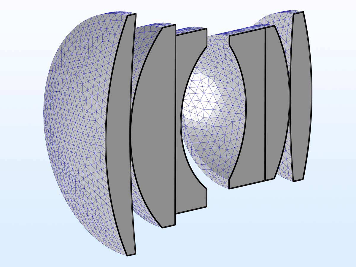 A cross section of a multielement lens constructed using multiple instances of the Spherical General Lens 3D part.
Circular Planar Annulus
The Circular Planar Annulus is a flat ring that can be inserted into 3D geometries to function as an aperture stop. For example, you can put these around the lenses in a camera or telescope to absorb stray light. The part may also be used without a central hole in order to provide a simple circular plane.
 A cross section of a lens with apertures that have been defined using Circular Planar Annulus part instances.
On Axis Conic Mirror
The On Axis Conic Mirror is an axisymmetric mirror where the radius of curvature and conic constant may be specified. You can also choose between having a central hole or not.
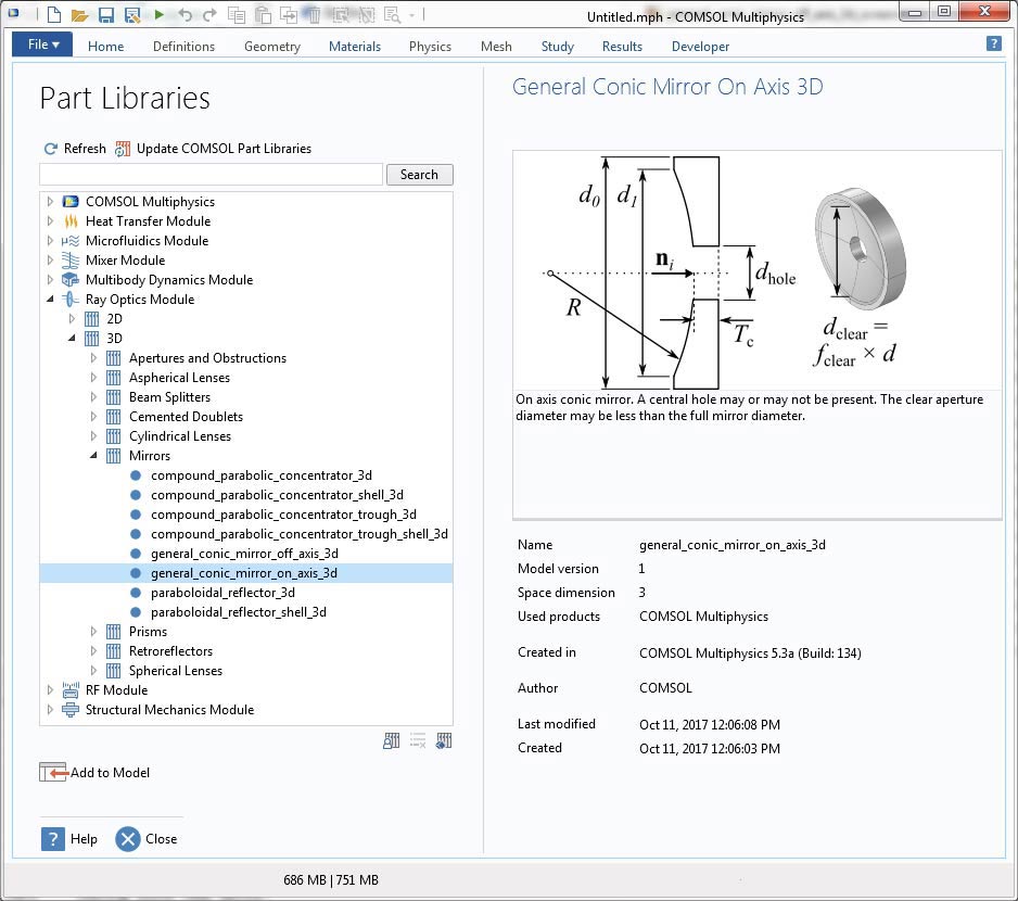
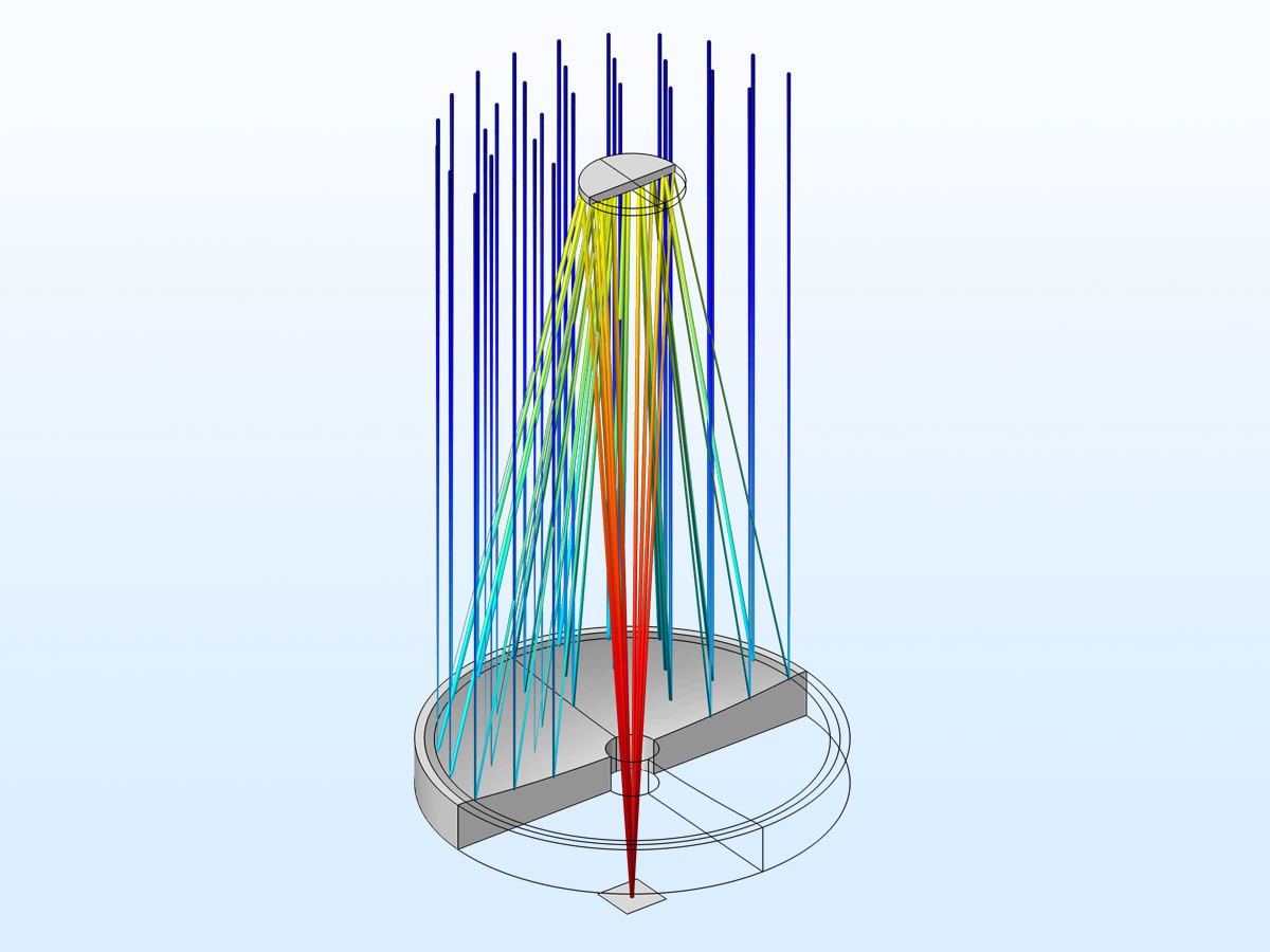 A simple two-mirror telescope model constructed using the On Axis Conic Mirror part instance. In addition to having a central hole, the primary mirror includes a clear aperture definition and a flat annulus on the front edge.
Off Axis Conic Mirror
The Off Axis Conic Mirror is a mirror in which the center is displaced from the axis of symmetry. As with the On Axis Conic Mirror, the radius of curvature and conic constant may be specified. The White Pupil Échelle Spectrograph tutorial in the Application Library demonstrates the use of this part, and is explained in more detail below.
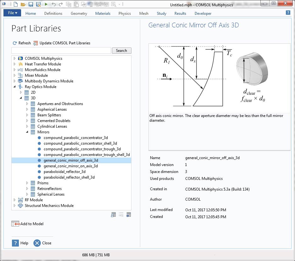
New Tutorial Models: Double Gauss Lens
Two new Double Gauss Lens tutorials have been added to the Application Library to demonstrate how to set up and postprocess a lens system with a simple multielement objective lens. The individual lenses are defined as part instances using the built-in Part Library for the Ray Optics Module. Two versions of this tutorial are available: a simpler version in which the Ray Tracing study is run once and a more elaborate version with a parametric sweep over different wavelengths and field angles.
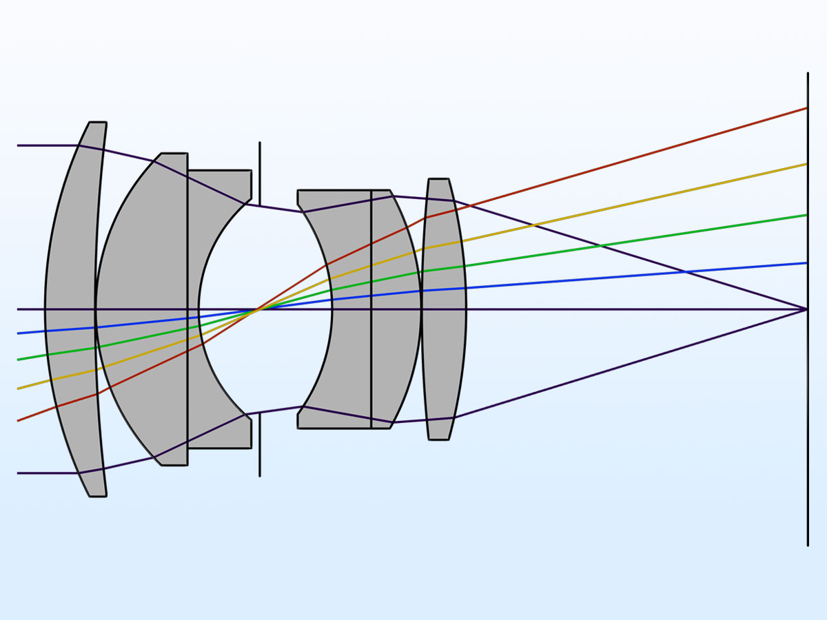 This cross-section view of the Double Gauss Lens shows the marginal on-axis rays as well as the chief rays at four additional field angles.
 The ray diagram of the Double Gauss Lens (Parametric Sweep) model using multiple wavelengths and field angles.
Application Library path:
Ray_Optics_Module/Lenses_Cameras_and_Telescopes/double_gauss_lens
Ray_Optics_Module/Lenses_Cameras_and_Telescopes/double_gauss_lens_parametric
New Tutorial Model: Petzval Lens
The new Petzval lens tutorial, similar to the Double Gauss lens tutorial, has been added to the Application Library to demonstrate how to set up and postprocess a lens system using multiple part instances from the built-in Part Library for the Ray Optics Module. In many cases, you may want to include a lens, such as the Petzval lens, in a larger system, which is demonstrated in the new White Pupil Échelle Spectrograph tutorial model (see below).
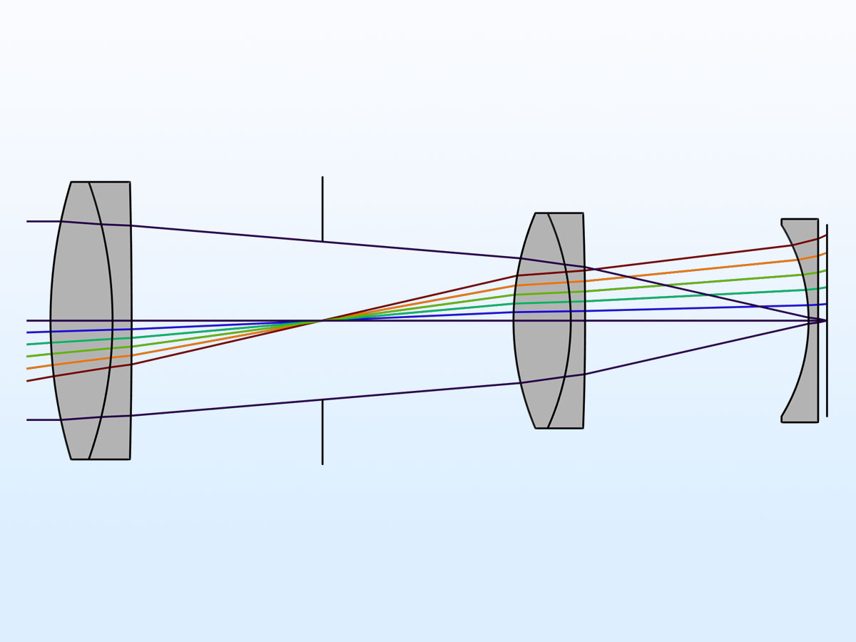 This cross-sectional view of the Petzval Lens model shows the marginal on-axis rays, as well as the chief rays at five additional field angles.
Application Library path:
Ray_Optics_Module/Lenses_Cameras_and_Telescopes/petzval_lens
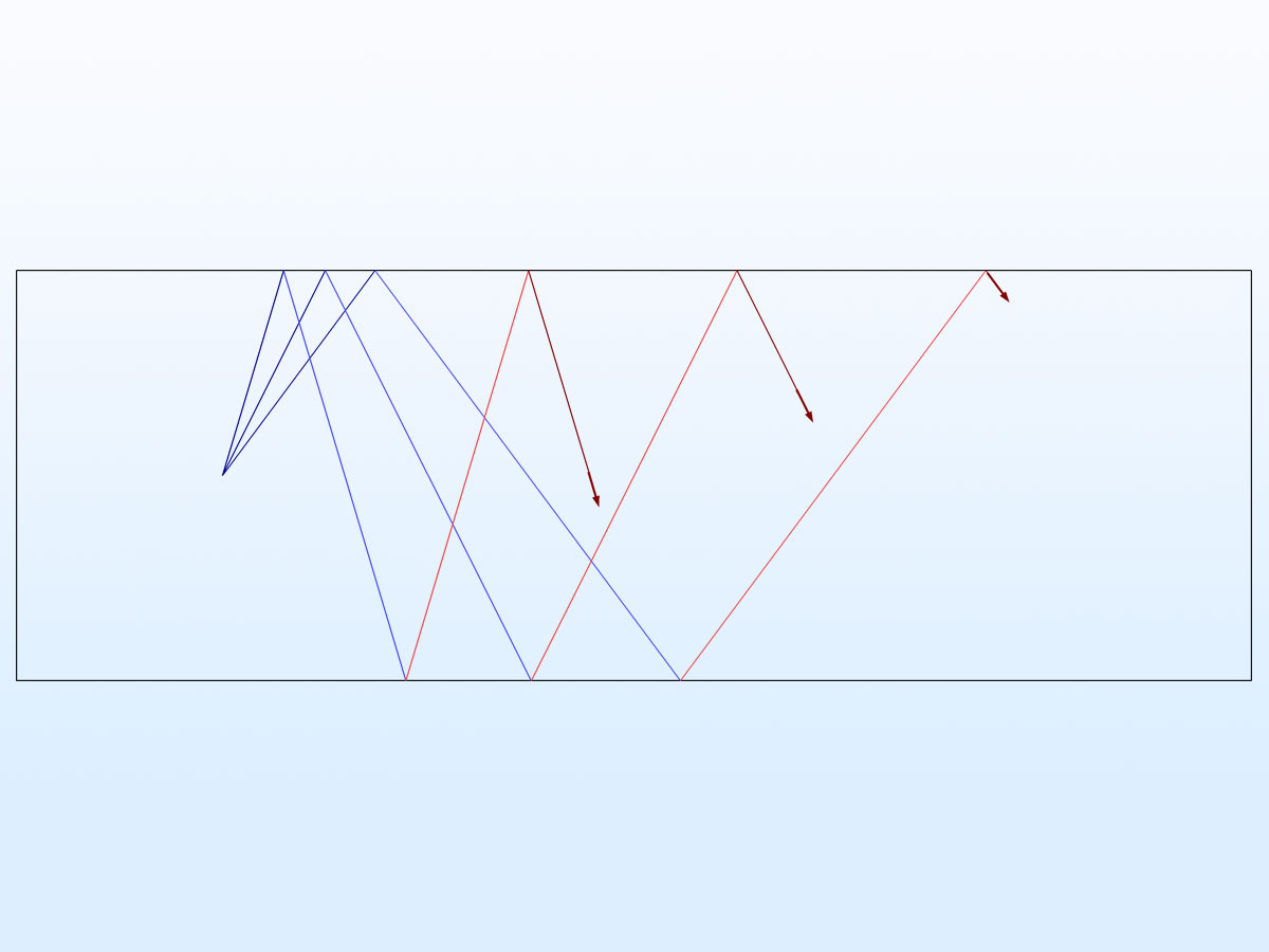
New Tutorial Model: White Pupil Échelle Spectrograph
An échelle spectrograph is an instrument consisting of gratings, mirrors, and lenses that can separate polychromatic light into a highly dispersed spectrum. In this tutorial, rays are traced through a fully parameterized geometry of an échelle spectrograph and focused by a Petzval lens. The model uses two gratings, the échelle grating (used in high order) and the cross-disperser grating, with different directions of periodicity, producing a 2D array of spots for different wavelengths and échelle orders.
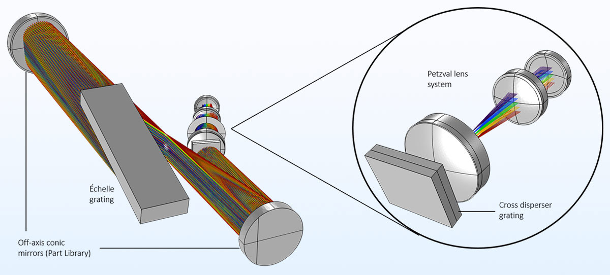 The white pupil échelle spectrograph. Rays are colored according to their vacuum wavelength. To the right is an expanded view of the Petzval lens system, filtered so that only the axial rays for each wavelength are shown.
Application Library path:
Ray_Optics_Module/Spectrometers_and_Monochromators/white_pupil_echelle_spectrograph