Rotordynamics Module Updates
For users of the Rotordynamics Module, COMSOL Multiphysics® version 5.3a brings six types of rolling element bearings, a new multiphysics coupling to connect rotordynamics models to solid models, and a new hydrodynamic thrust bearing. Learn about these rotordynamics features below.
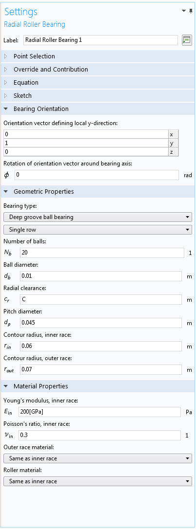
Rolling Element Bearing
Models for six types of rolling element bearings have been added to the Rotordynamics Module:
- Deep groove ball bearing
- Angular contact ball bearing
- Self-aligning ball bearing
- Spherical roller bearing
- Cylindrical roller bearing
- Tapered roller bearing
Each of the bearings can have either a single row or a double row of rolling elements. The model includes a nonlinear representation of the contact stiffness between the rolling elements and the inner and outer races.
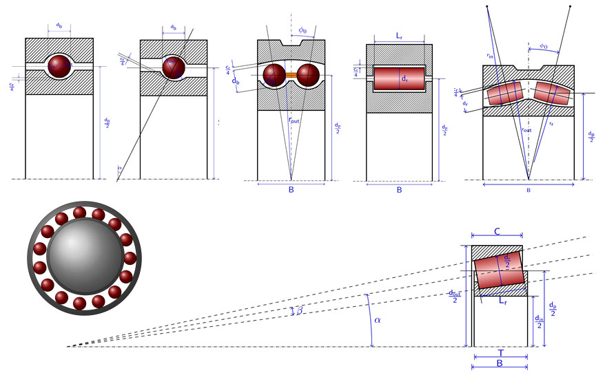
Sketches of the six different bearing types and their geometrical parameters. The front view (bottom left) illustrates how only a certain number of the rolling elements carry load.
Coupling Hydrodynamic Bearings to Solid Models
A new multiphysics coupling, Solid-Bearing, has been added to connect a journal bearing modeled in the Hydrodynamic Bearing interface to a moving solid part from the Solid Mechanics or Multibody Dynamics interfaces. The bearing can either be considered as fixed or as mounted on a flexible part.
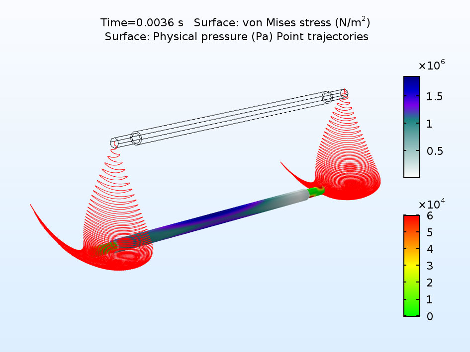
A flexible shaft, modeled with the Multibody Dynamics Module, rotating in a hydrodynamic journal bearing. The pressure distribution in the bearing depends strongly on the bending of the shaft.
Hydrodynamic Thrust Bearing
The Hydrodynamic Bearing interface can now also solve for a Hydrodynamic Thrust Bearing, a new feature included in the release of COMSOL Multiphysics® version 5.3a. The bearing types can either be Tilted Pad, Tapered, or User Defined. The tilted pad bearing can have either a point pivot or a line pivot. Additionally, cavitation of the lubricant can be included in the formulation.
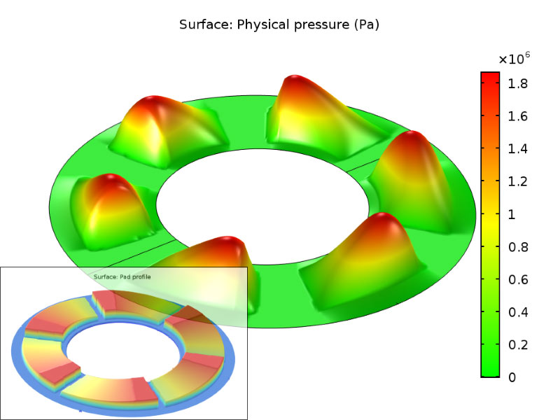
Pressure distribution and pad profile in a thrust bearing.
Improved Default Plots
The default plots in the structural mechanics physics interfaces have been updated to produce more informative visualizations. The Application Library tutorials have been updated accordingly. Some of the more prominent changes that you will see are as follows:
- The color table for von Mises stress plots is RainbowLight
- The color table for mode shape plots, for eigenfrequency and linear buckling studies, is AuroraBorealis
- Mode shape plots have the legend switched off to emphasize that the amplitude of a mode does not have a physical meaning
- The color table for section force plots in the Beam and Truss interfaces is Wave, with a symmetric color range
- This makes it possible to immediately distinguish between tension and compression, for example
- In contact analysis, a plot of the contact pressure is added, as either a line plot (2D) or contour plot (3D)
- The default plot for Stress Linearization now has a legend for the graphs
- The default Undeformed geometry plot, produced by the Shell interface, has new colors
- When a material model like plasticity or creep is used, a contour plot of a relevant strain quantity, like the effective plastic strain, overlays the stress plot
- Applicable for the Nonlinear Structural Materials Module and the Geomechanics Module
- In the Fatigue interface, the Traffic color table is used for predicted cycles to failure and for usage factors
- Applicable for the Fatigue Module
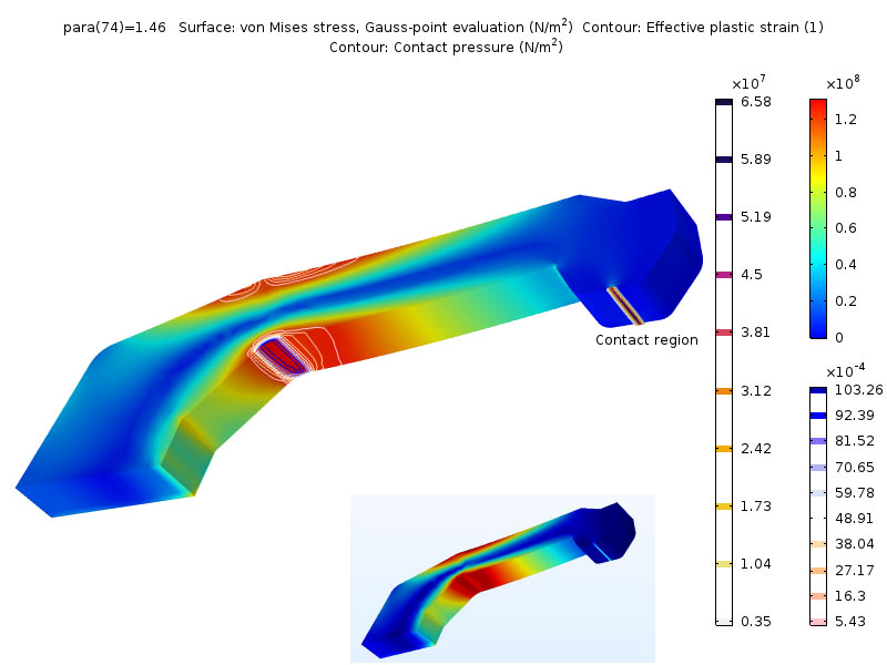
In this example, you can see brighter colors in the stress plot (RainbowLight color table), and plastic strain contours and contact pressure contours have been added by default. For comparison, a plot from the default plot in COMSOL Multiphysics® version 5.3 of the same model is shown.
New Tutorial Model: Stability of a Turbocharger Influenced by Cross-Coupled Bearing Forces
Cross-coupled forces present in a hydrodynamic bearing often act as negative damping in a rotor. Near the critical speed, this may lead to uncontrolled vibration of the turbocharger, causing a risk of bearing failure. In this example, you can analyze the influence of the cross-coupling forces on the dynamics of the rotor. Part of the study includes how to reduce these vibrations.
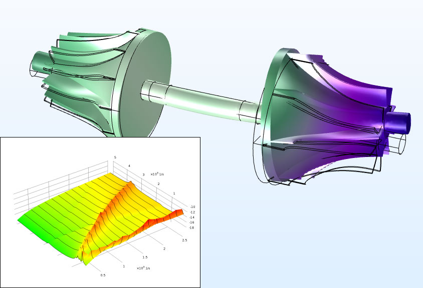
First eigenmode of the system at 500 RPM and a waterfall diagram showing displacement amplitude as function of RPM and excitation frequency.
Application Library path:
Rotordynamics_Module/Automotive_and_Aerospace/turbocharger_stability_analysis
New Tutorial Model: Effect of Roller Bearing Clearance on Nonsynchronous Vibration of a Rotor
Bearing clearances should be kept at a minimum to avoid nonsynchronous vibration of a rotor. However, a tight clearance reduces the durability of the bearing. This tutorial model compares the vibration induced by nonlinear contact for different radial clearances.
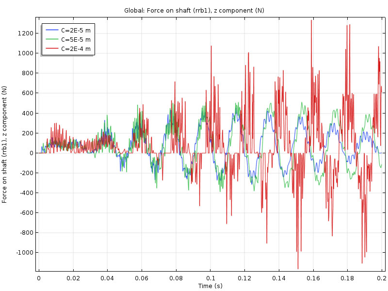
Dynamic response for different values of the bearing clearance; the highest clearance leads to an instability with high and intermittent bearing forces.
Application Library path:
Rotordynamics_Module/Tutorials/nonsynchronous_rotor_vibration_with_roller_bearing