COMSOL Desktop® Updates
For all COMSOL Multiphysics® software users, version 5.6 introduces a number of Graphics window enhancements, including interactive clipping functionality and context menus. Read more about these and other COMSOL Desktop® updates below.
Graphics Window Improvements
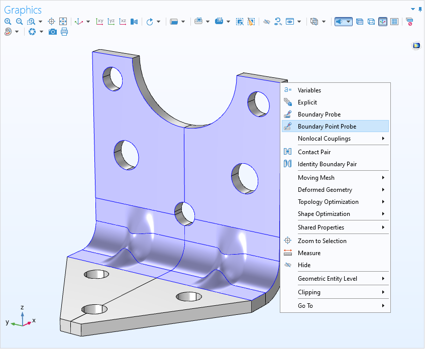
The Graphics window context menu, introduced for physics in COMSOL Multiphysics® version 5.5, now supports many more options, including definitions, geometry, mesh, materials, and multiphysics. By right-clicking and choosing from a context menu, this method simplifies selections throughout the modeling workflow. The Graphics toolbar has new options for YX, ZY, or ZX views. In addition, you can control whether the x-axis, y-axis, or z-axis should be used as the vertical axis in the default 3D view. There is a new option in the Preferences window for making the Graphics window toolbar buttons larger, which can be useful for high-resolution monitors, and another for changing the COMSOL Desktop® color theme.
Interactive Clipping
To make it easier to select edges, boundaries, and domains that are located inside a surrounding object, you can now use interactive clipping. Add planes, boxes, cylinders, and spheres to select which parts of a geometry are shown. The interactive clipping functionality works throughout the Model Builder and is available from a menu button in the Graphics toolbar. When you click the toolbar button, by default, a Clip Plane node is added to the View node, with settings that you can adjust in a Settings window or interactively in the Graphics window. Multiple clip planes may be added and used concurrently.
