Electric Currents
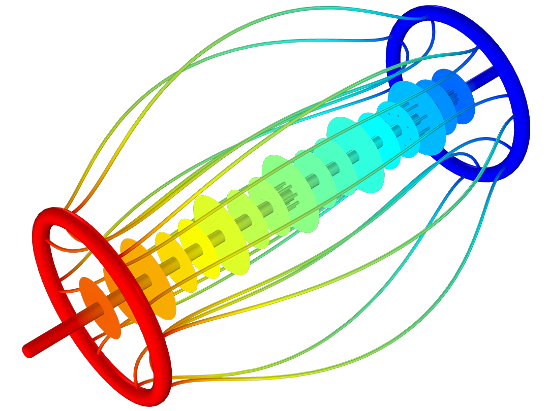
Analyze resistive and conductive devices efficiently by modeling DC, transient, or AC currents. Under static and low-frequency conditions, and when magnetic fields are negligible, modeling electric currents is sufficient for accurate results. The computations, based on Ohm's law, are made very efficient by solving for the electric potential. Based on the resulting potential field, a number of quantities can be calculated: resistance, conductance, electric field, current density, and power dissipation.
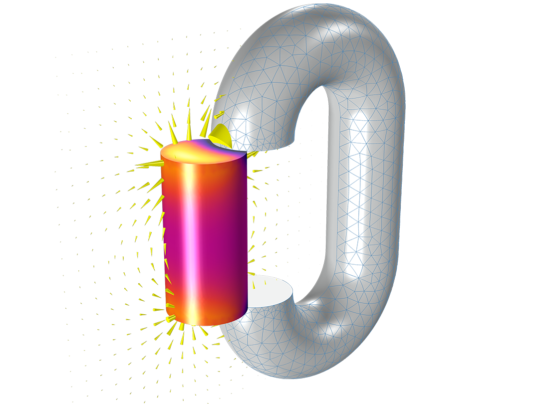
With the AC/DC Module, you can run stationary, frequency-domain, and time-domain analyses, as well as small-signal analysis. In the time and frequency domains, you can also account for capacitive effects.