support@comsol.com
Battery Design Module Updates
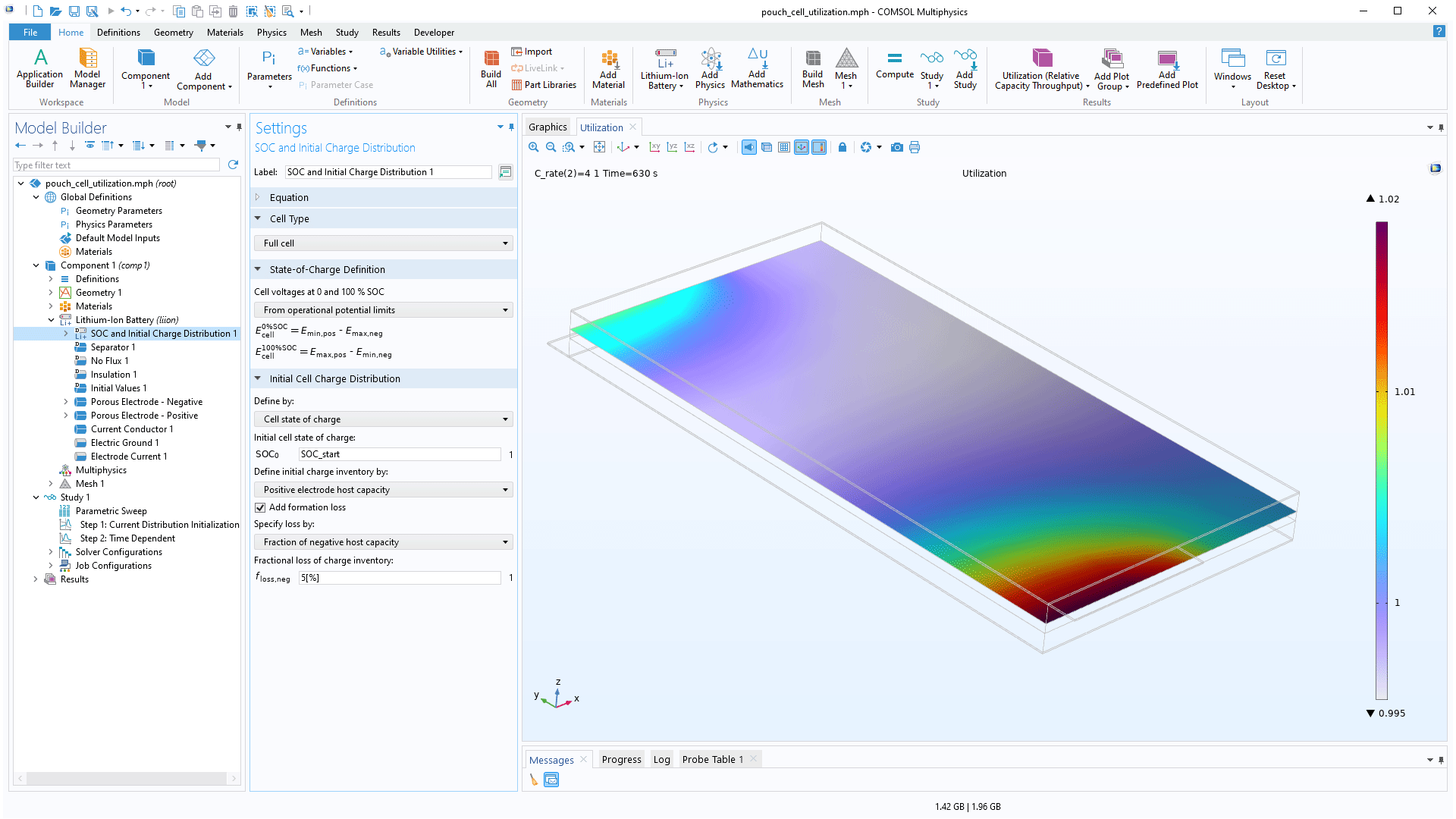
For users of the Battery Design Module, COMSOL Multiphysics® version 6.2 provides a new SOC and Initial Cell Charge Distribution feature to automatically define state-of-charge (SOC) and state-of-health (SOH) cell-level variables, as well as functionality to include external contact resistances for various boundary conditions and the ability to define anisotropic tortuosities. Learn about these updates below.
New SOC and SOH Cell-Level Variables and Improved Framework for Setting the Initial Cell Charge Distribution
A new SOC and Initial Cell Charge Distribution feature is available in the Lithium-Ion Battery and Battery with Binary Electrolyte interfaces that automatically defines cell-level SOC and SOH variables. In the settings of the interface, selecting the Enable state of charge (SOC) and initial charge distribution check box will add the SOC and Initial Cell Charge Distribution node to the Model Builder. This feature can also be used to set an initial cell-level charge distribution based on an initial cell SOC, an open-circuit cell voltage, individual electrode potentials, or individual electrode charge inventories. You can view these updates in the following tutorial models:
- pouch_cell_utilization
- li_battery_rate_capability
- li_battery_internal_resistance
- li_battery_drive_cycle
- diffusion_induced_stress
- capacity_fade_
- li_battery_solid_electrolyte
- li_battery_multiple_materials_1d
Contact Resistance
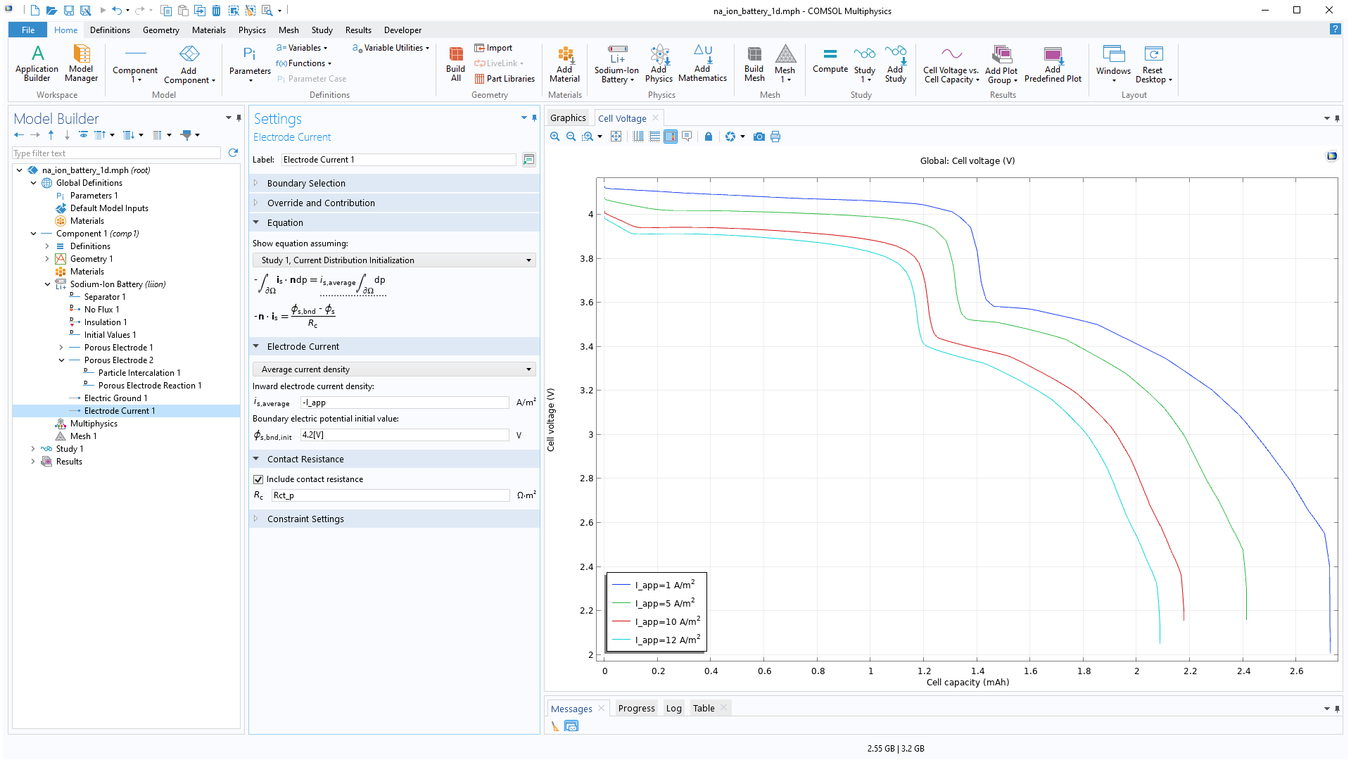
For the electrochemistry interfaces, external contact resistances can now be included for the Electric Ground, Electric Potential, Electrode Current, and Electrode Power boundary conditions. In the Battery Pack interface, internal contact resistances can be included in the Negative Connectors and Positive Connectors boundary conditions. This feature can be enabled by the Include contact resistance check box in the Settings window, and the desired resistance can also be specified in the text field.
Anisotropic Tortuosities
For the Lithium-Ion Battery and Battery with Binary Electrolyte interfaces, tortuosity can now be defined using anisotropic Diagonal or Symmetric tensors in the Porous Electrode, Separator, Porous Conductive Binder, and Highly Conductive Porous Electrode features. For all of the aforementioned features, the tensor setting can be applied in the Effective Transport Parameter Correction section of the settings to specify, for example, different in-plane and through-plane diffusivity and conductivity values. Additionally, the Transport of Concentrated Species interface now supports anisotropic tortuosities in porous media.
New and Updated Tutorial Models
COMSOL Multiphysics® version 6.2 brings several new and updated tutorial models to the Battery Design Module.
1D Isothermal Sodium-Ion Battery
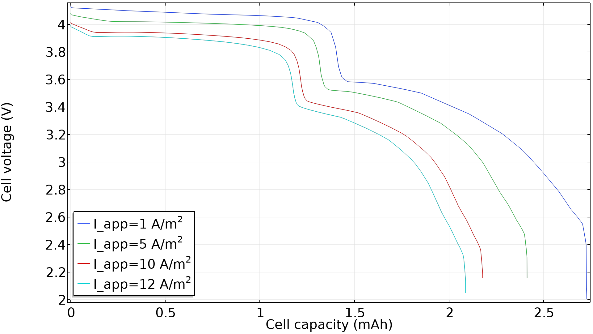
Application Library Title:
sodium_ion_battery_1d
Download from the Application Gallery
Silicon–Graphite-Blended Electrode with Thermodynamic Voltage Hysteresis
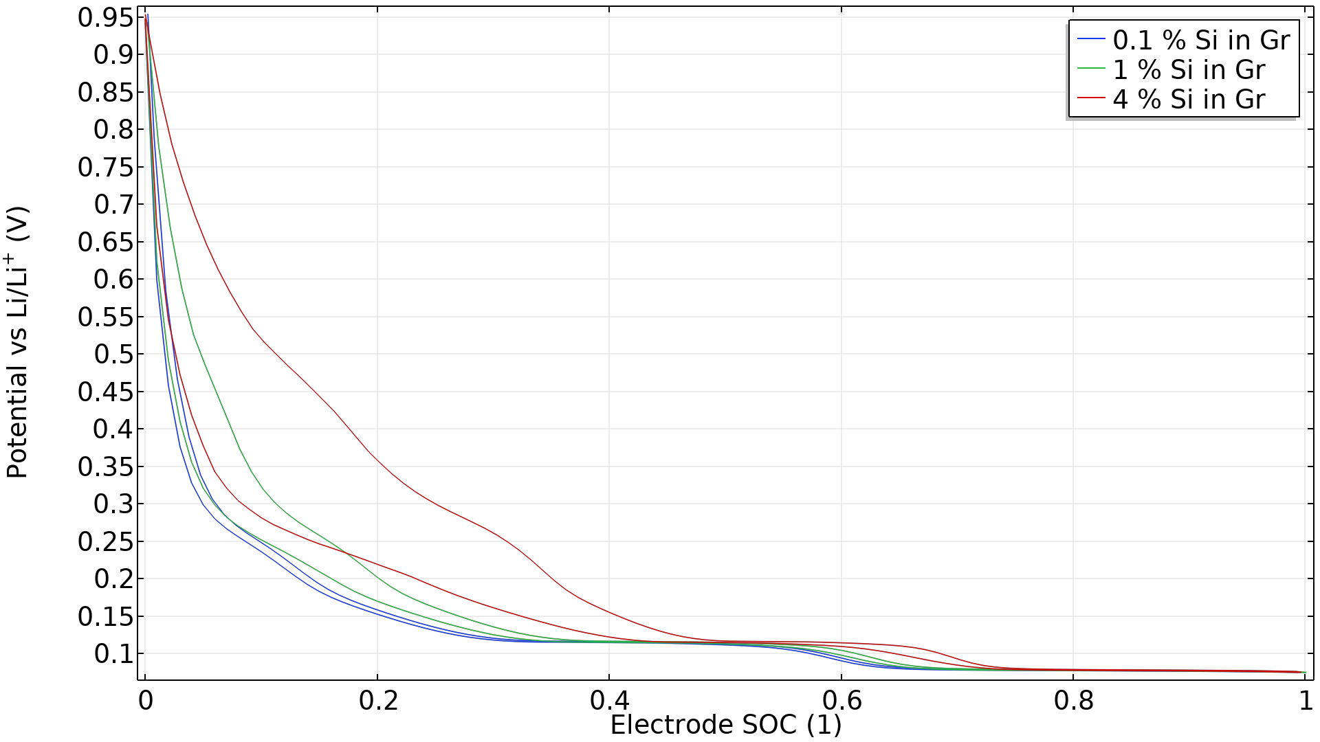
Application Library Title:
sigr_hysteresis
Download from the Application Gallery
Battery Electrode with a Particle Size Distribution
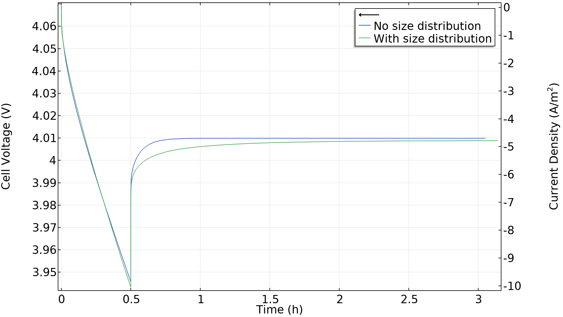
Application Library Title:
particle_size_distribution
Download from the Application Gallery
Surrogate Model Training of a Battery Rate Capability Model
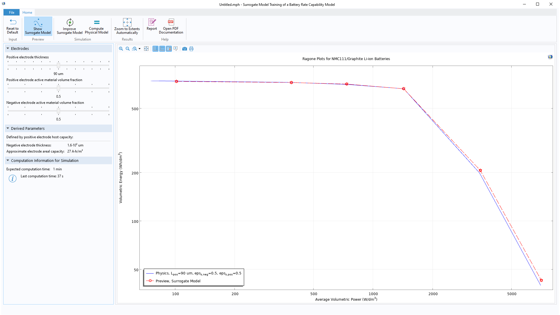
Application Library Title:
lib_rate_capability_surrogate
Download from the Application Gallery