support@comsol.com
Structural Mechanics Module Updates
For users of the Structural Mechanics Module, COMSOL Multiphysics® version 6.2 introduces a Phase Field in Solids interface, a virtual crack extension method for the evaluation of fracture mechanics, and a feature that enables static analysis of accelerated unconstrained structures. Read about these updates and more below.
New Phase Field in Solids Interface
Phase-field modeling can be used for numerous physics applications, and a new Phase Field in Solids interface has been introduced in this version. This is a specialized interface for the modeling of phenomena involving moving interfaces within solids, such as the propagation of cracks, damage evolution, and the growth of grain boundaries.
New Transport in Solids Interface
A new Transport in Solids interface has been added for modeling transport of species, electromigration, hydrogen embrittlement, and other transport phenomena in solid materials. The interface allows for stationary and time-dependent studies of transport involving one or several species. In addition, if the diffusion problem is stress driven, the Transport in Solids interface can be coupled with a Solid Mechanics interface.
New Unsaturated Poroelasticity Multiphysics Coupling
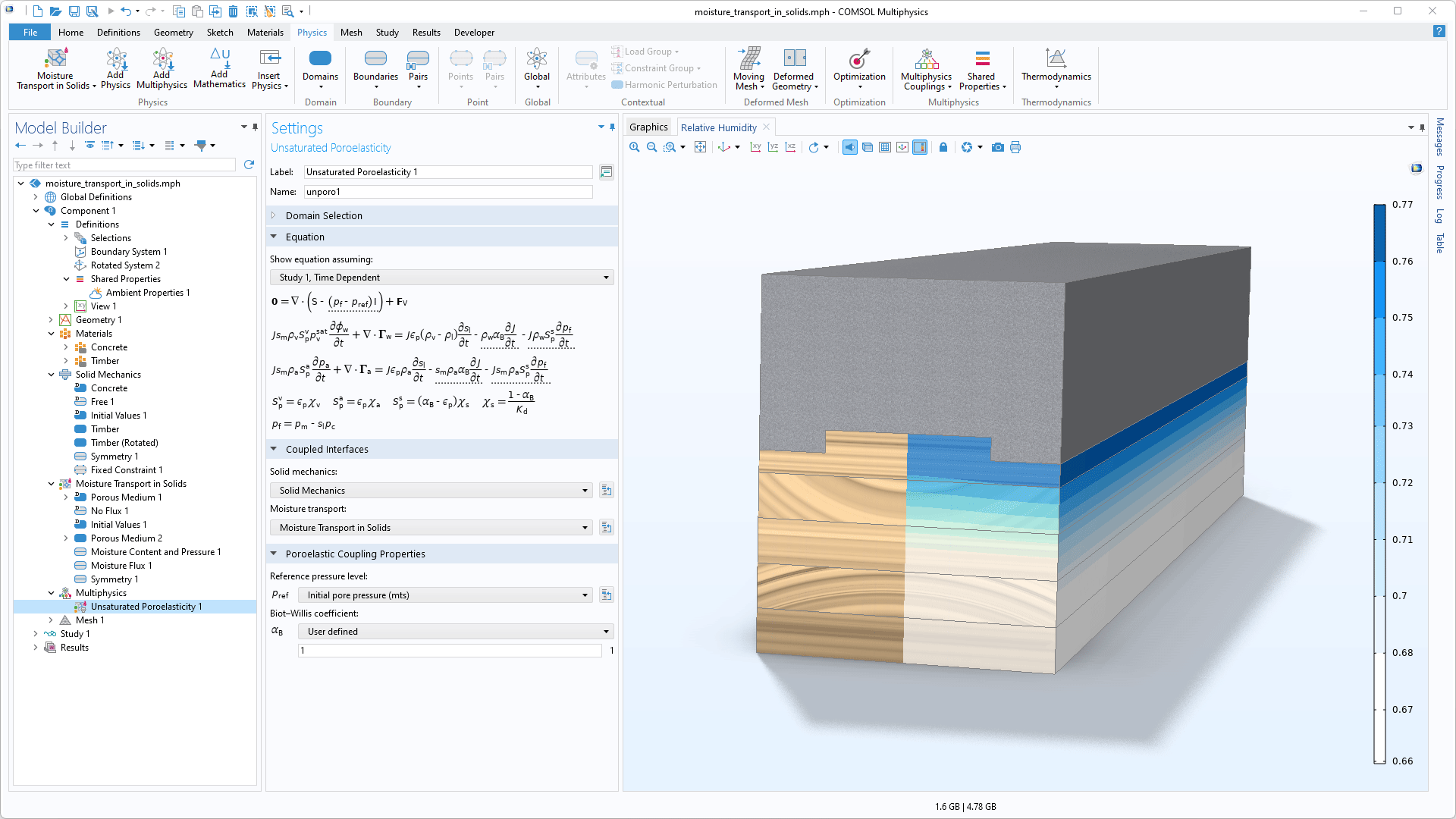
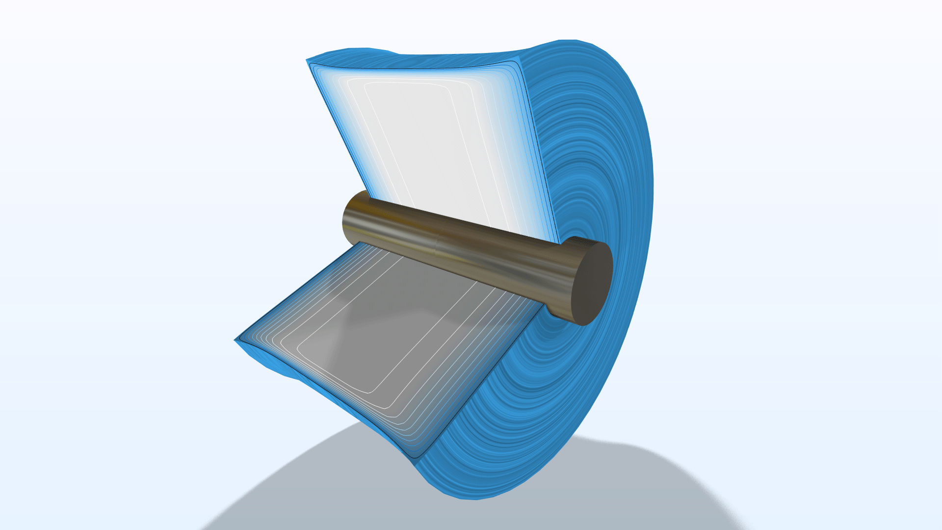
A new multiphysics coupling, Unsaturated Poroelasticity, has been added to link a Moisture Transport in Solids interface with a Solid Mechanics interface. This two-way coupling imposes the moisture pressure as a load in the pores, while resulting structural deformations modify the storage coefficients and porosity. These kinds of studies can easily be configured using the new Unsaturated Poroelasticity multiphysics interface, which automatically adds a Moisture Transport in Solids interface, a Solid Mechanics interface, and an Unsaturated Poroelasticity multiphysics coupling. The Moisture Transport in a Paperboard Roll tutorial model showcases this new functionality. Note that this feature requires the Porous Media Flow Module or the Heat Transfer Module.
New Magnetic–Elastic Interaction in Rotating Machinery Multiphysics Interface
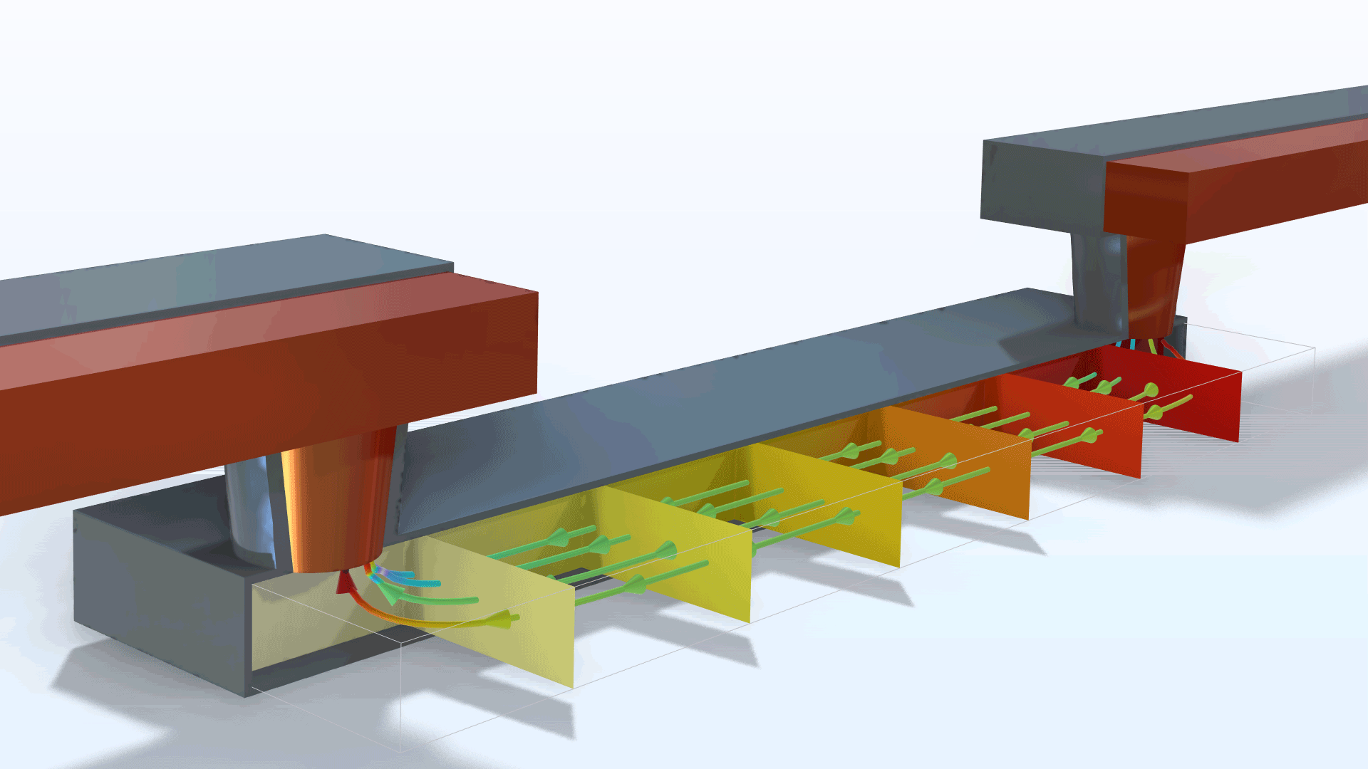
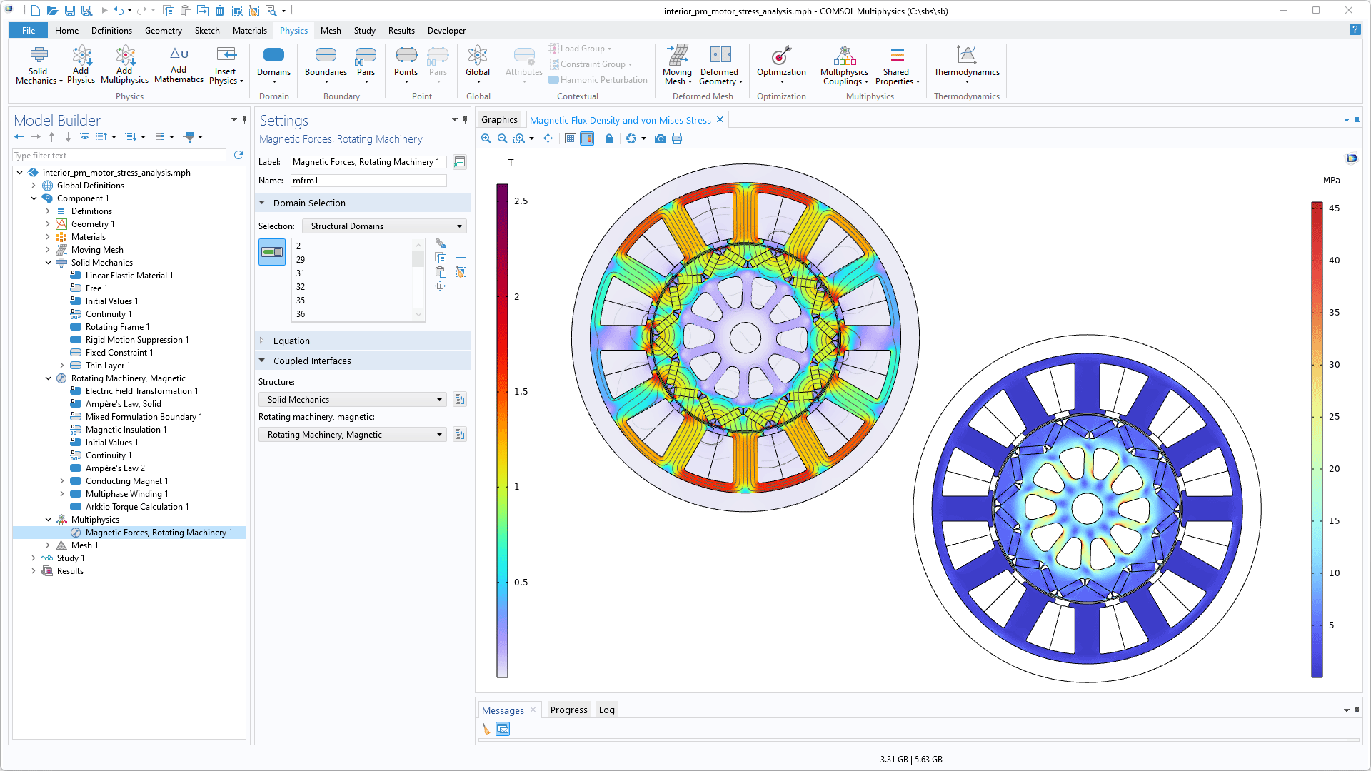
In some rotating components, such as electric motors, you may need to take into account the bidirectional coupling between the magnetic field and the structural deformations. The new Magnetic–Elastic Interaction in Rotating Machinery multiphysics interface couples a Solid Mechanics interface and a Rotating Machinery, Magnetic interface together with moving mesh features. A new multiphysics coupling, Magnetic Forces, Rotating Machinery, is used to apply the loads originating from magnetic Maxwell stresses on a compliant rotating structure. At the same time, deformation caused by a combination of magnetic loads and centrifugal forces will affect the magnetic field. An example of how this interface can be used to investigate the deformations and stress distribution in an electrical motor is shown in the new Electromagnetic and Mechanical Analysis of an Interior Permanent Magnet Motor model. Note that this feature and tutorial model require the AC/DC Module.
New Thermal Expansion, Thin Layer Multiphysics Coupling
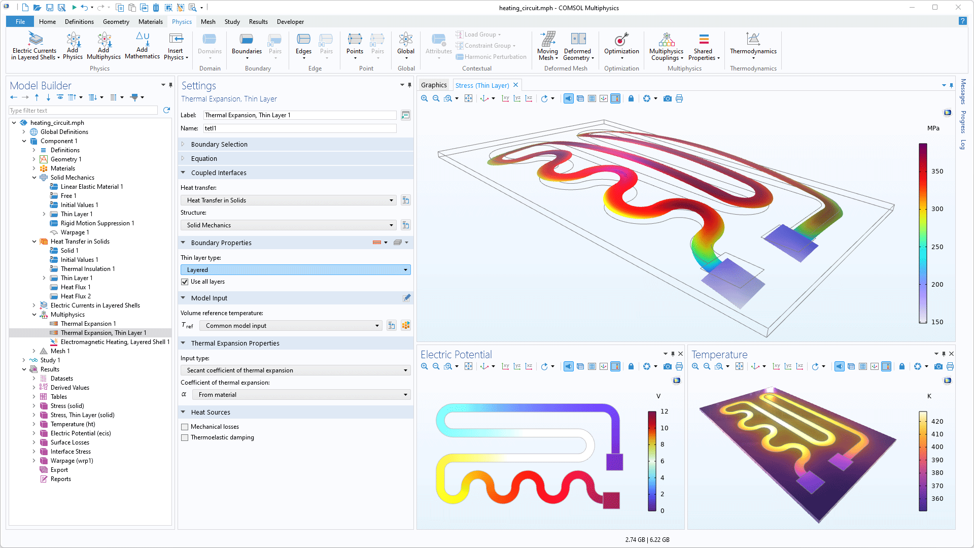
The new Thermal Expansion, Thin Layer multiphysics coupling node enables the thermal expansion in boundaries that have a Thin Layer material model to be coupled with the temperature field on the same boundaries computed in a Heat Transfer interface. This new functionality can be seen in the updated Heating Circuit tutorial model.
Unconstrained Structures When Modeling Contact
Contact problems often involve insufficient constraints until contact has been established. As a result, the stiffness matrix becomes singular. A new Stabilization feature has been added to alleviate this inherent difficulty. The Prestressed Bolts in a Tube Connection and Prestress of Main Bearing Cap Bolts tutorial models have been updated to illustrate the use of this feature.
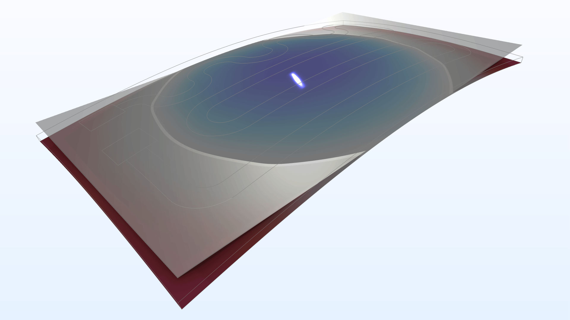
Computation of Warpage
In some applications, such as PCBs, a planar surface must retain a sufficient degree of planarity in order for the structure to function correctly after loads have been applied. A new Warpage feature has been added to the Solid Mechanics, Shell, and Layered Shell interfaces to evaluate the deviation of a surface from its original shape. The use of this new functionality is demonstrated in the updated Thermal Stresses in a Layered Plate and Heating Circuit tutorial models.
Fluid-Filled Cavities
A new Enclosed Cavity feature has been added to the Solid Mechanics interface. This feature provides the ability to model enclosed, fluid-filled cavities without the need to mesh the cavity itself. The pressure in the cavity acts as a load on the structure, and the volume of the cavity is controlled by the structural deformations. There are several available equations of state for the contents of a cavity (contents such as isothermal or adiabatic gas or incompressible fluid). This new functionality is demonstrated in the Hyperelastic Seal and Biventricular Cardiac Model tutorial models.
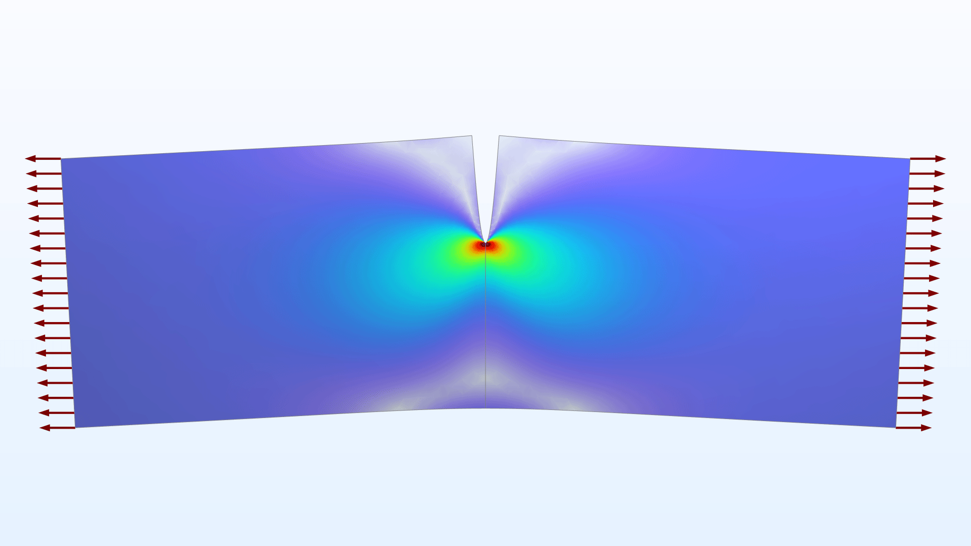
Virtual Crack Extension Method
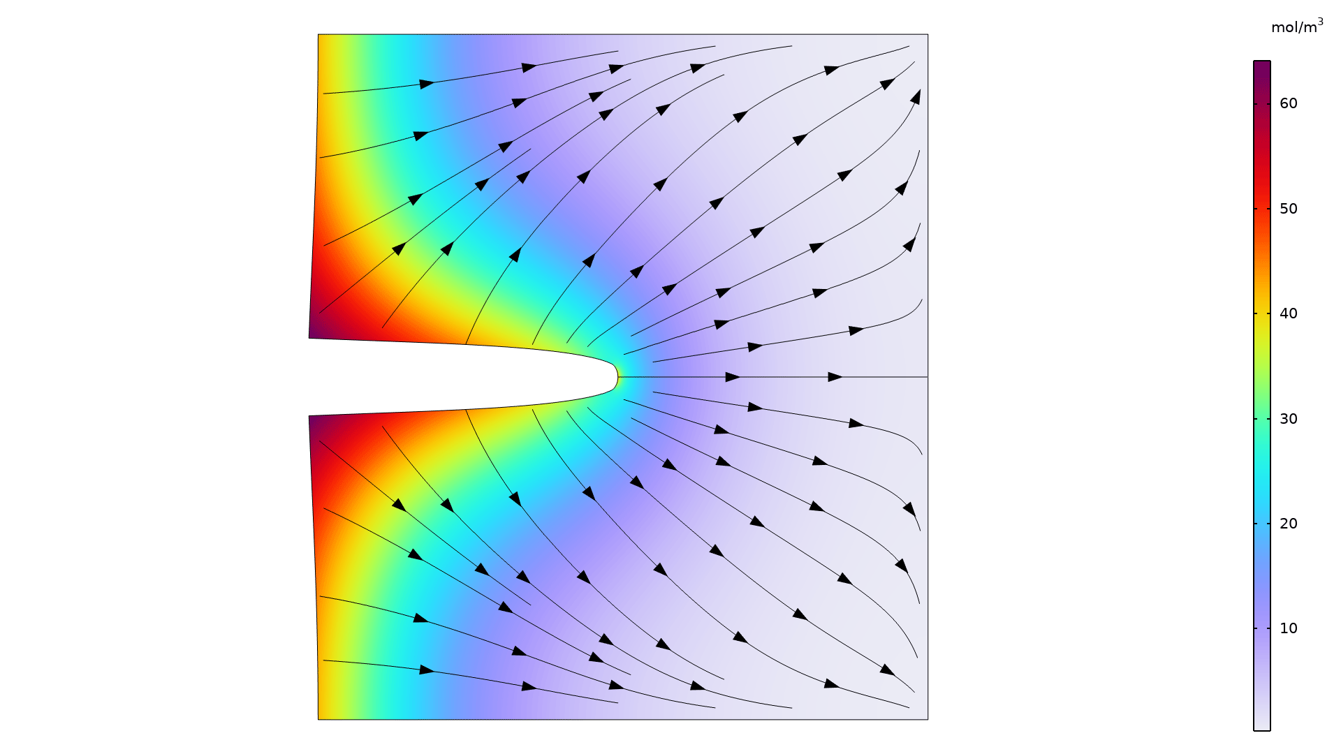
A new Virtual Crack Extension feature has been added as an alternative to the J-integral method for determining energy release rates and stress intensity factors. With this new feature, you can perform the same analyses but also account for body loads and thermal expansion. This feature is used in the updated Single Edge Crack tutorial model.
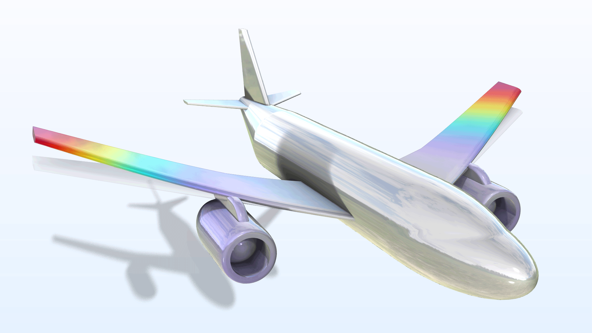
Inertia Relief Analysis
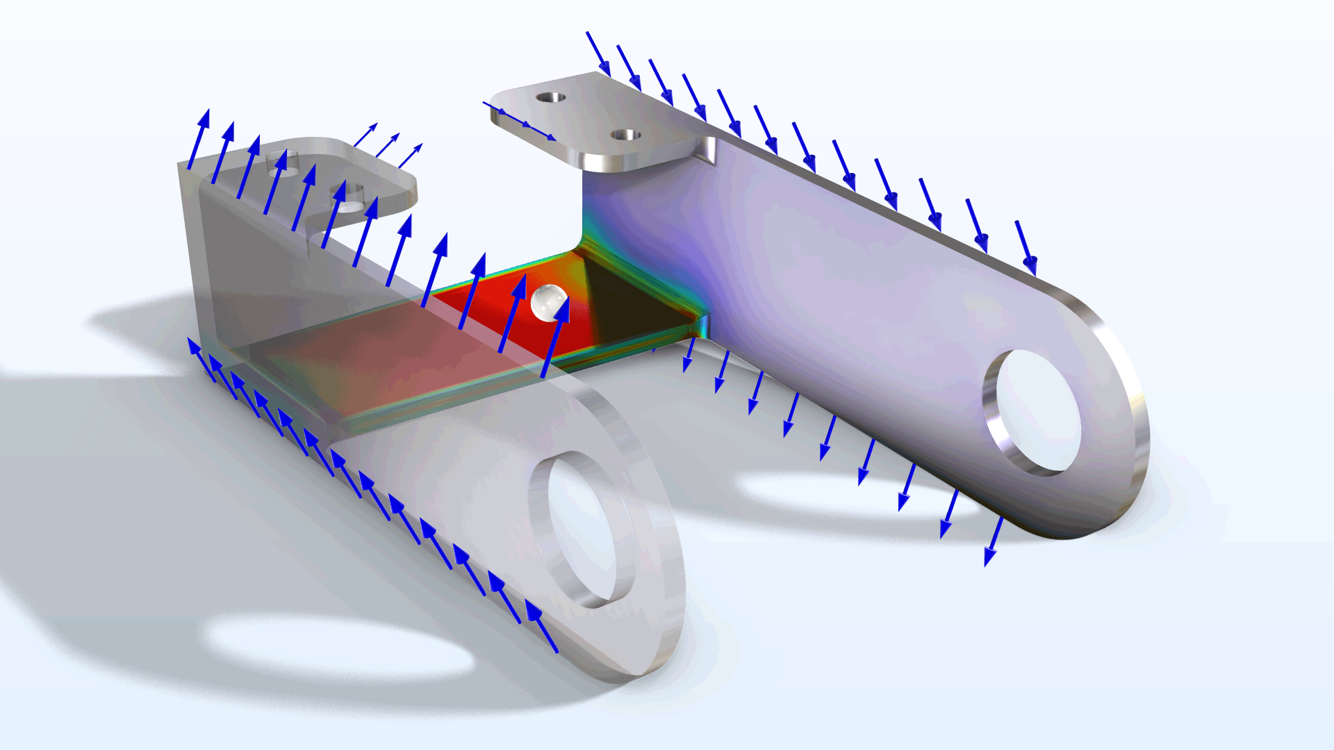
Inertia relief analysis is a special type of static analysis for unconstrained structures that are accelerated by external loads, where the external loads and inertial forces of the structure must maintain a dynamic force balance. In all of the Structural Mechanics interfaces, a new Inertia Relief feature has been added. This feature can be used to automate the setup of a special study sequence that computes the acceleration field, the corresponding inertia forces, and the resulting stresses. This new feature is used in the updated Bracket — Structural Mechanics Tutorials.
Piezoelectric Material, Layered Feature in Shell Interface
For the Shell interface, a new Piezoelectric Material, Layered feature is available. This new feature saves both assembly and computation time when solving thin piezoelectric composites. Note that this new feature requires either the AC/DC Module or MEMS Module. If the Composite Materials Module is also available, the feature can be used in multilayered shells, where the individual layers can have different material properties.
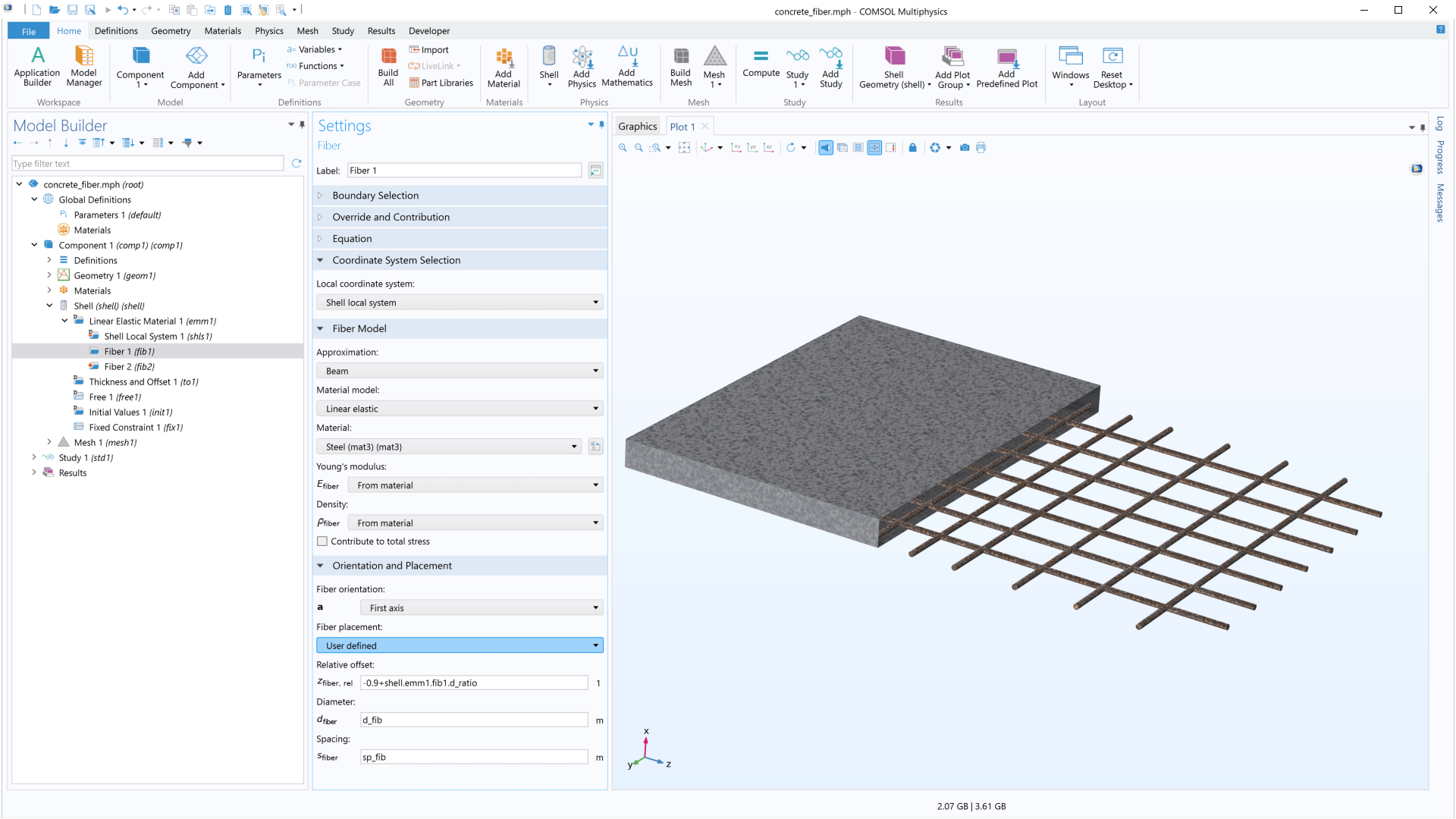
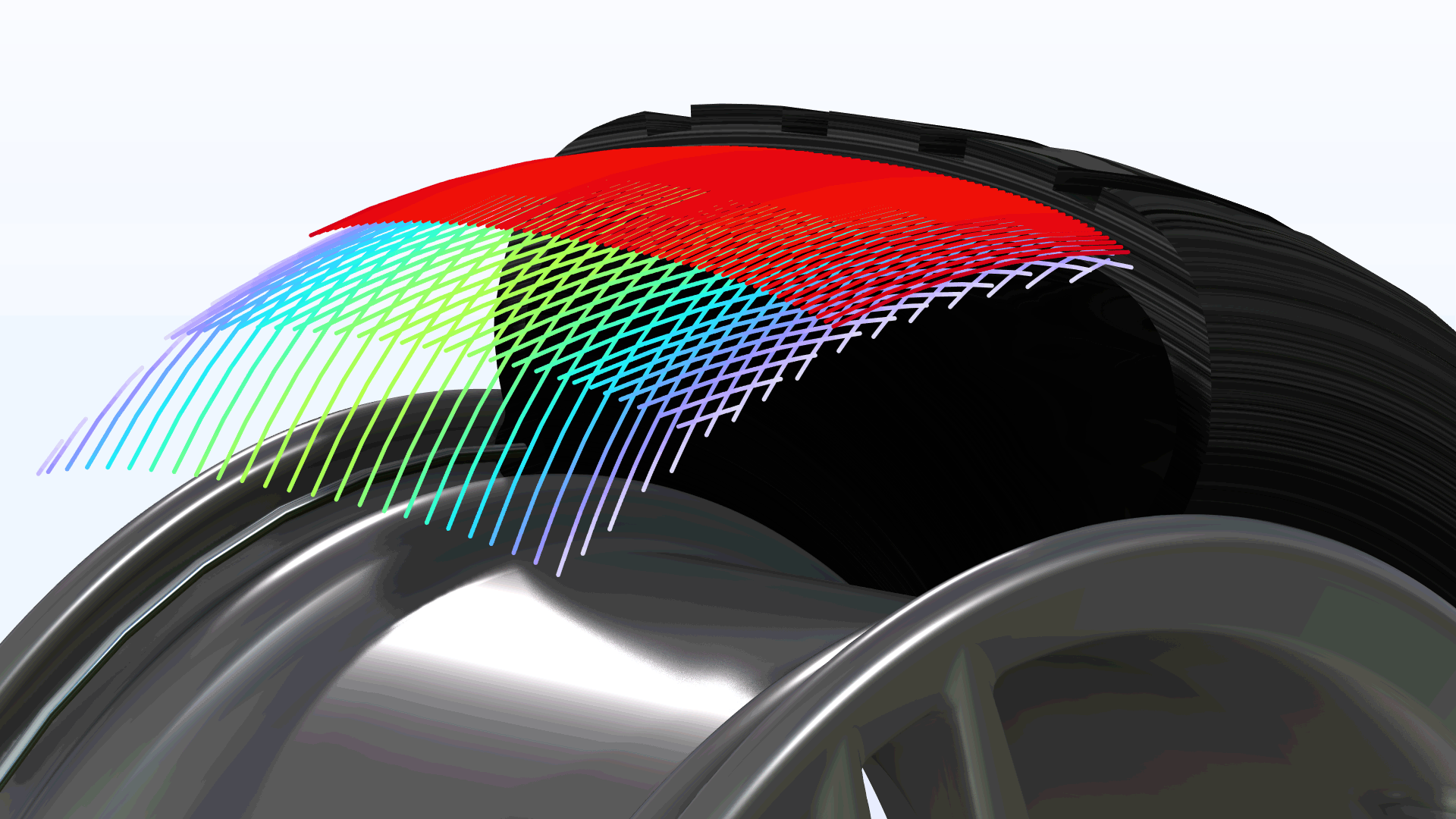
Enhancements to Fiber Functionality
The ability to add a distribution of fibers to a material by adding a Fiber subnode was introduced in version 6.0. In version 6.2, there are several extensions to this functionality. For instance:
- This functionality is now also available in the Shell interface. In this context, fibers can also be assigned a bending stiffness and a through-thickness location.
- The material model of the fiber can now be a general nonlinear function between stress and strain.
- The Fiber subnode can now also be added to material models in a Thin Layer feature.
You can see these updates in the new Tire Inflation tutorial model.
Limited Displacement
The possibility to prescribe a limited displacement (that is, the maximum distance that a point, edge, or boundary can move in a certain direction) has been added to the Solid Mechanics, Multibody Dynamics, Shell, Layered Shell, and Membrane interfaces. This functionality can be viewed as a simplified version of contact analysis, where no second object is needed to stop the movement. In previous versions, this functionality was only available in the edge-type interfaces, such as Beam or Truss, and therefore was only applicable to edges or points.
Updates to the Octave Band Plot
The Octave Band plot can now be used to analyze results based on a transient simulation. The transient data is transformed to the frequency domain before being analyzed. The Octave Band plot now also has a General (non-dB) input type that can be used to analyze absorption data in acoustics or vibration velocity data to plot a frequency response function (FRF) in a structural vibrations model.
New and Updated Tutorial Models
COMSOL Multiphysics® version 6.2 brings several new and updated tutorial models to the Structural Mechanics Module.
Elastic Cloaking with Polar Material
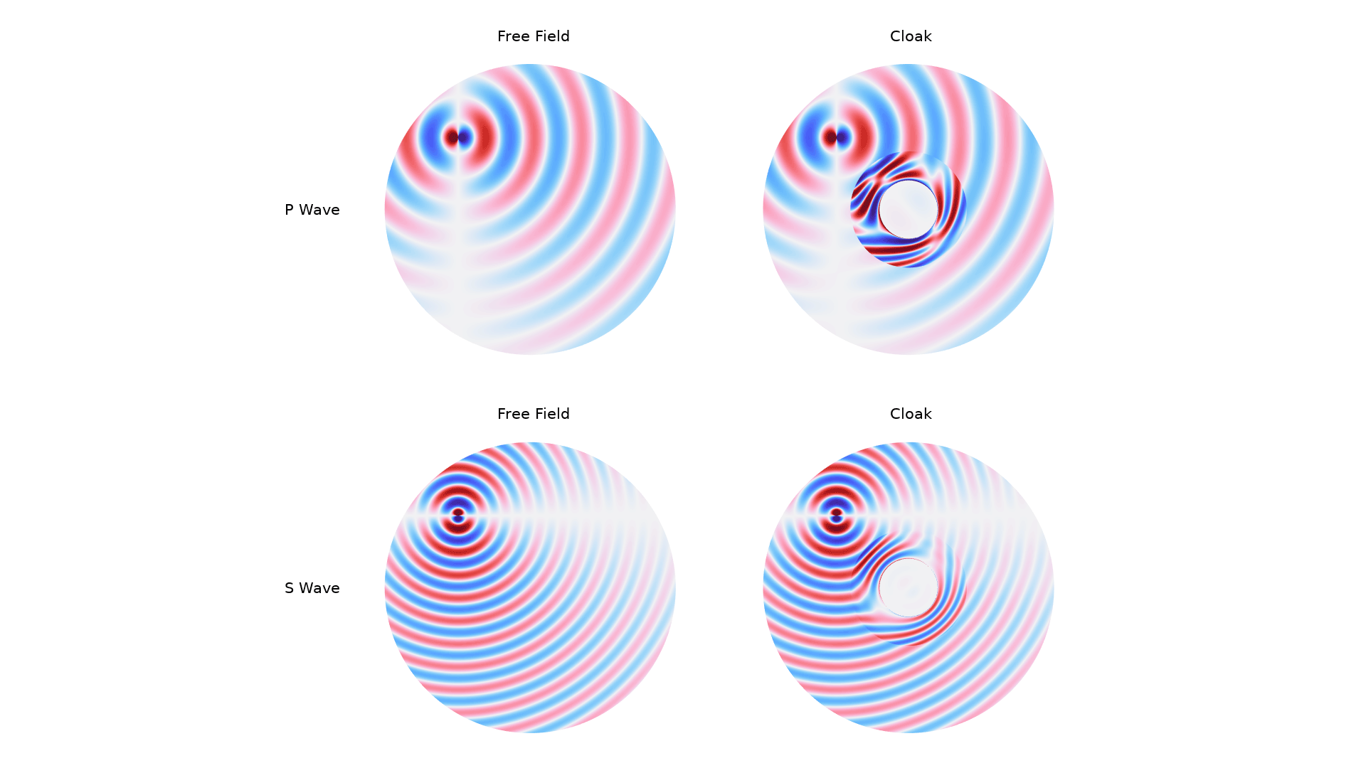
Application Library Title:
elastic_cloaking
Download from the Application Gallery
Scattered-Field Formulation for Elastic Waves
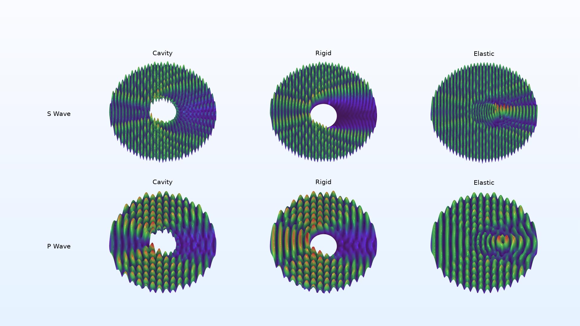
Application Library Title:
scattered_field_elastic_waves
Download from the Application Gallery
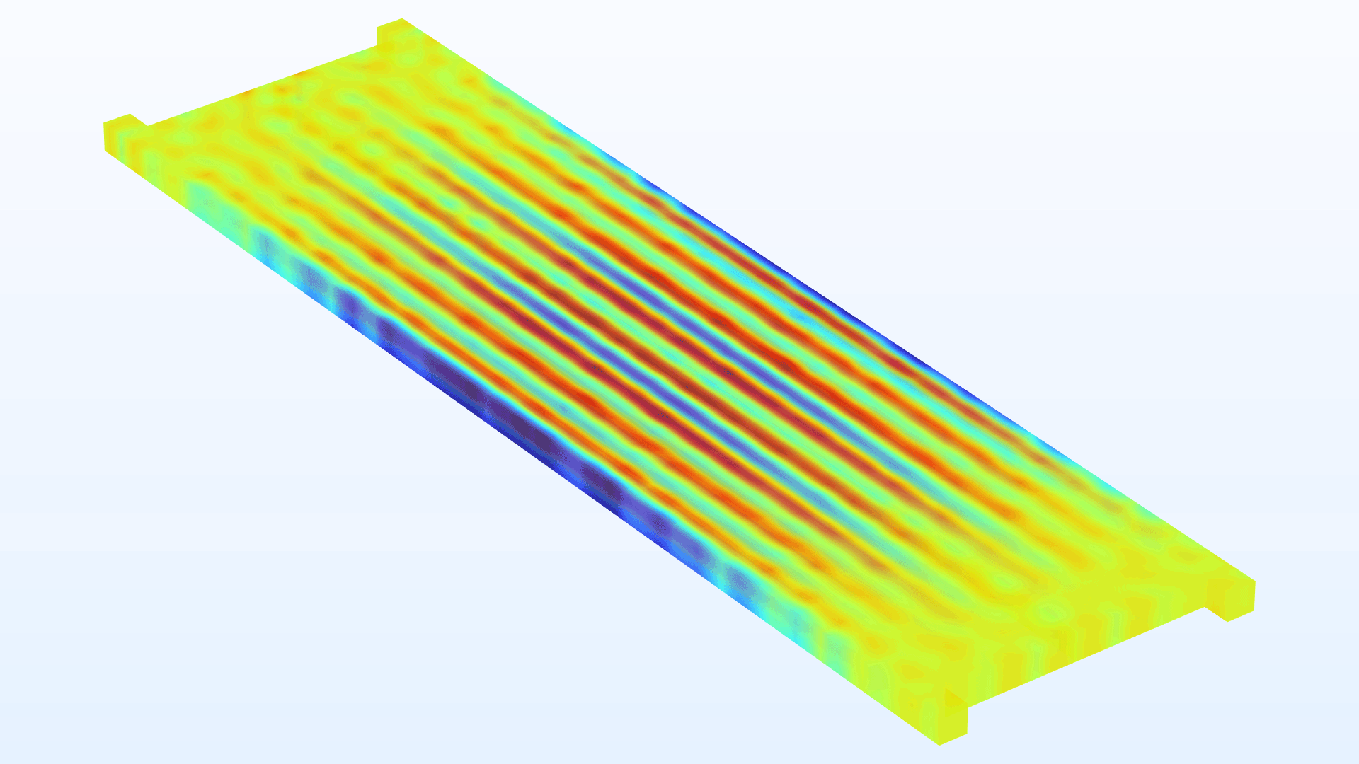
Homogenized Model of a Corrugated Sheet
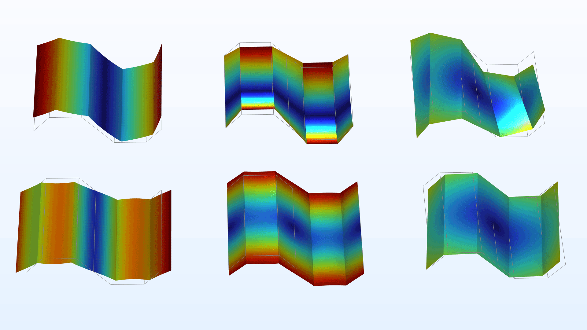
Application Library Title:
corrugated_sheet
Download from the Application Gallery
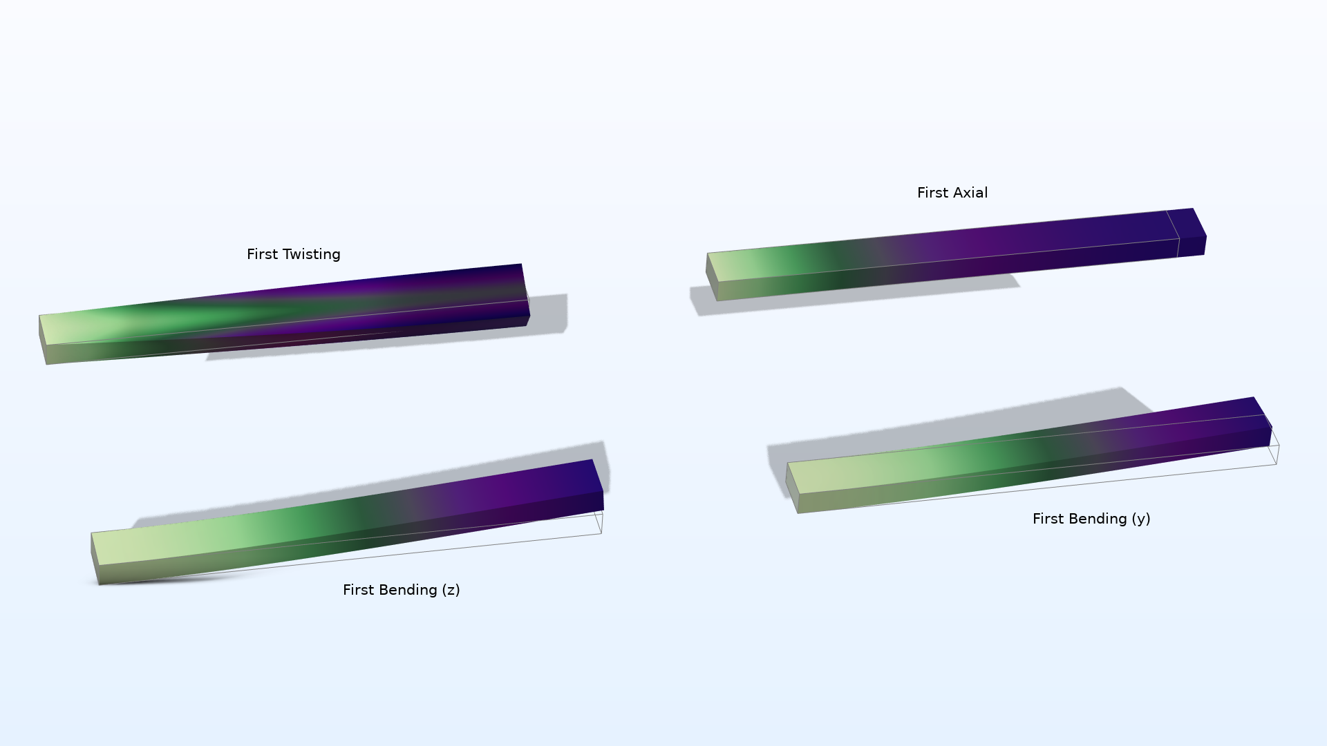
Ladder Frame
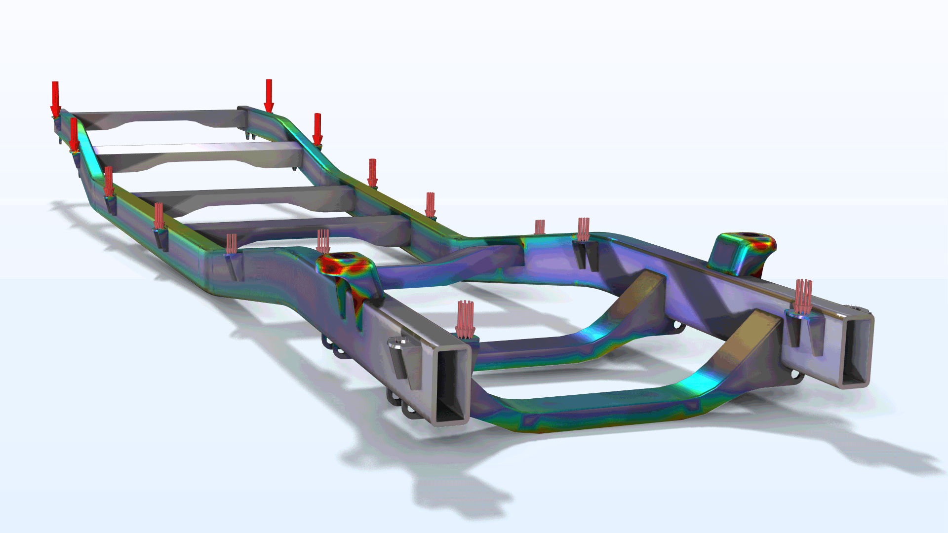
Application Library Title:
ladder_frame
Download from the Application Gallery
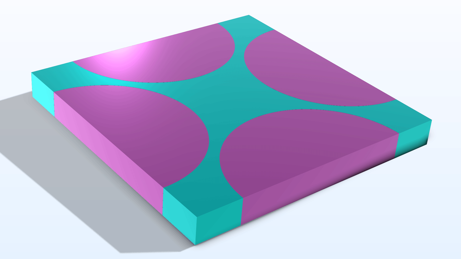
Micromechanical Model of a Triply Periodic Minimal Surface (TPMS)-Based Composite
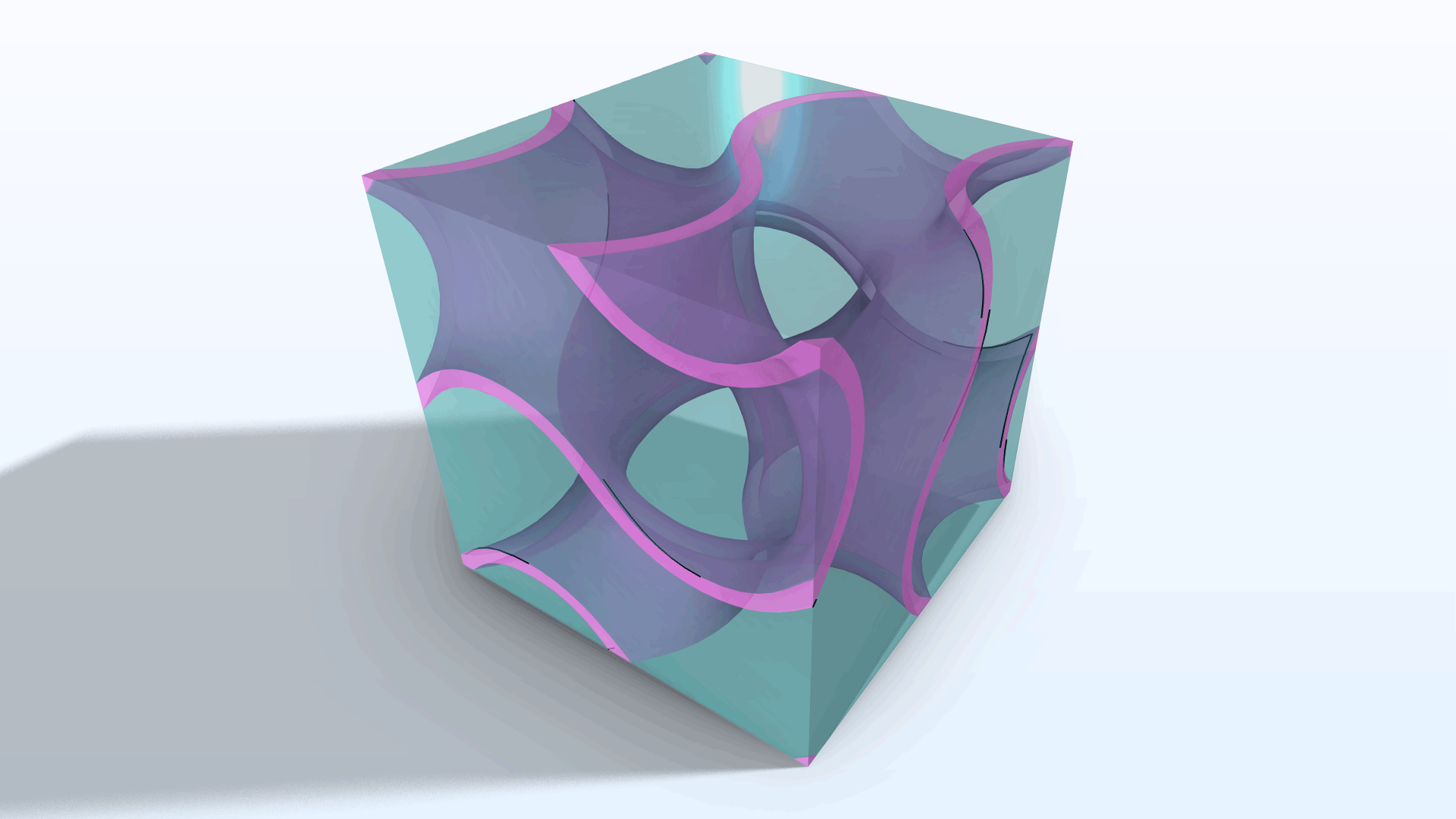
Application Library Title:
micromechanical_model_of_a_tpms_composite
Download from the Application Gallery
Eigenfrequency Shifts Caused by Temperature Changes
Application Library Title:
frequencyshift
Download from the Application Gallery
Micromechanical Model of a Piezoelectric Fiber Composite
Application Library Title:
micromechanical_model_of_a_piezoelectric_composite
Download from the Application Gallery
Postbuckling Analysis Using an Incremental Arc Length Method
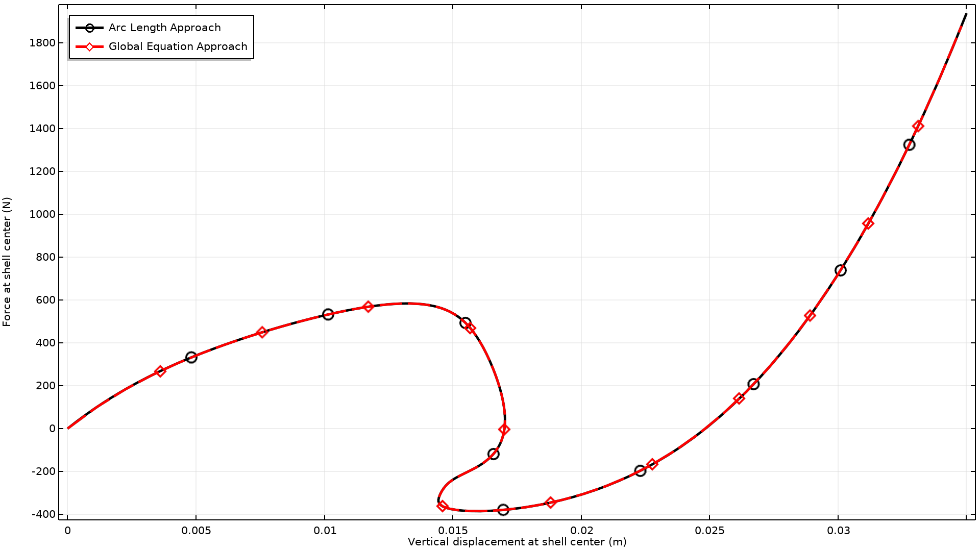
Application Library Title:
postbuckling_shell_arclength
Download from the Application Gallery
Vacancy Electromigration in Integrated Circuit (IC) Interconnect Lines
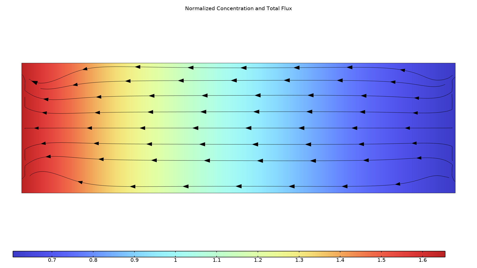
Application Library Title:
vacancy_electromigration
Download from the Application Gallery
Electromagnetic and Mechanical Analysis of an Interior Permanent Magnet Motor
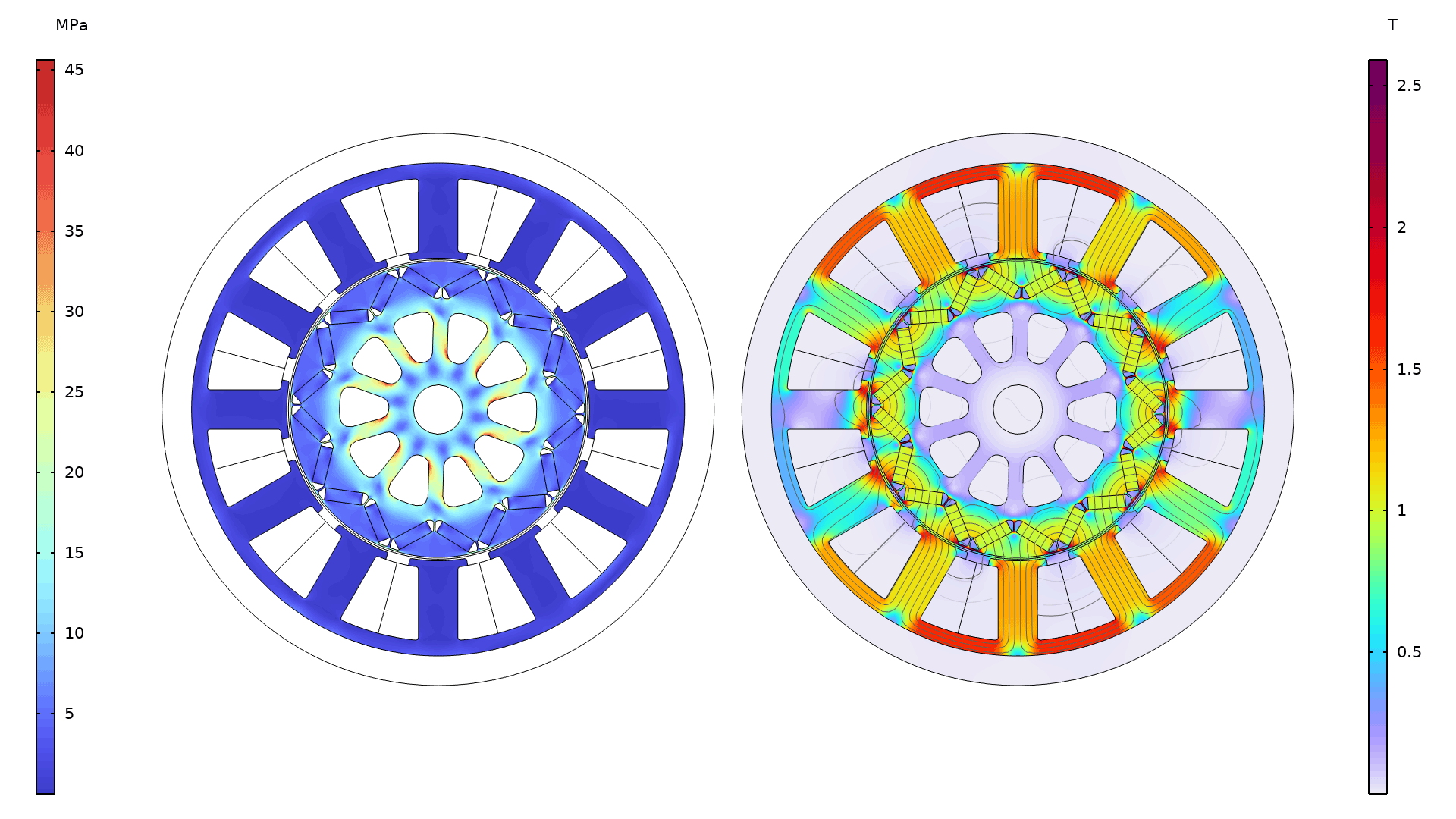
Application Library Title:
interior_pm_motor_stress_analysis
Download from the Application Gallery
Hydrogen Diffusion in Metals
Application Library Title:
hydrogen_diffusion
Download from the Application Gallery
Bracket — Inertia Relief Analysis
Application Library Title:
bracket_inertia_relief
Download from the Application Gallery
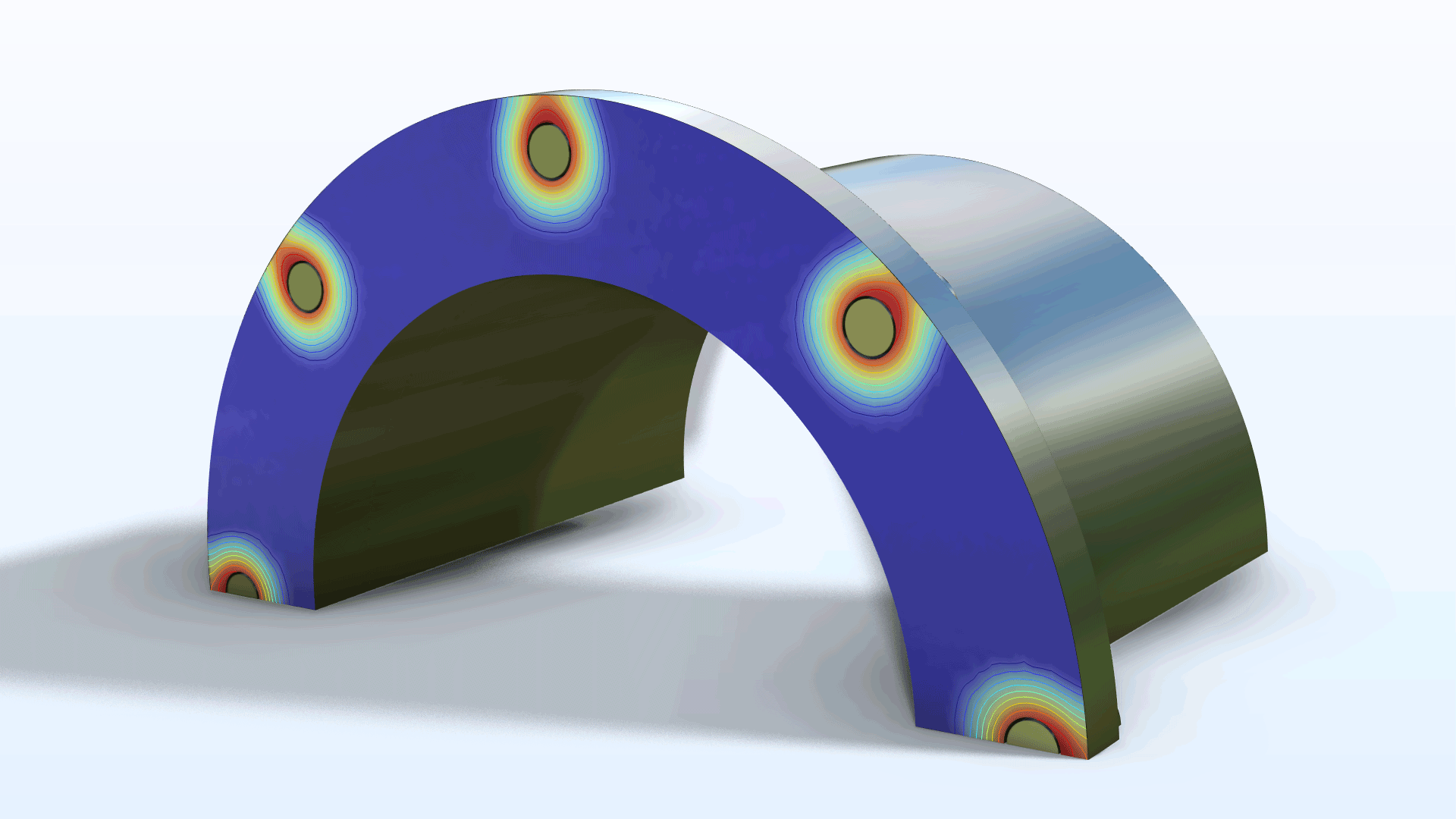
Moisture Transport in a Paperboard Roll*
Application Library Title:
paperboard_roll
Download from the Application Gallery
*Requires the Porous Media Flow Module
Bracket — Harmonic Vibration Fatigue (requires the Fatigue Module)
Application Library Title:
bracket_fatigue_harmonic_vibration
Download from the Application Gallery