support@comsol.com
MEMS Module Updates
For users of the MEMS Module, COMSOL Multiphysics® version 6.2 introduces a new interface for modeling piezoresistivity in multilayer structures, a new Thermal Expansion, Thin Layer multiphysics coupling, and a new Slip Wall boundary condition. Read about these updates and more below.
Note: The MEMS Module also inherits many new features from the updates to the Structural Mechanics Module.
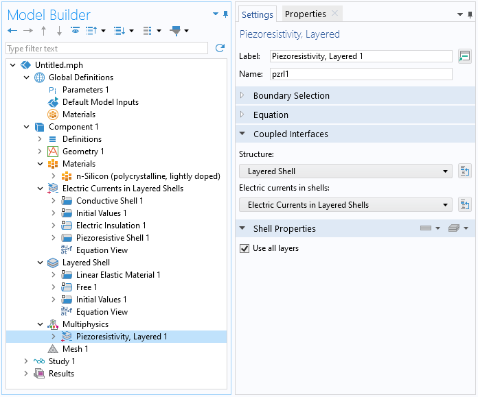
Piezoresistivity, Layered Shell Multiphysics Interface
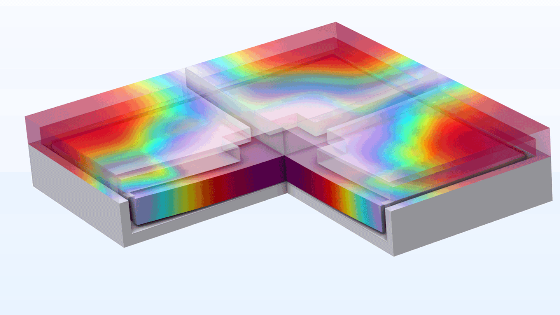
A new Piezoresistivity, Layered Shell multiphysics interface is available for modeling piezoresistivity in multilayer structures. It combines the Electric Current in Layered Shells interface with a Layered Shell interface and adds the new Piezoresistivity, Layered multiphysics coupling to the model tree. Note that this feature requires the Composite Materials Module.
Piezoelectric Material, Layered Feature in Shell Interface
For the Shell interface, a new Piezoelectric Material, Layered feature is available. This new feature saves both assembly and computation time when solving thin piezoelectric composites. Note that this new feature requires the Structural Mechanics Module. If the Composite Materials Module is also available, the feature can be used in multilayered shells, where the individual layers can have different material properties.
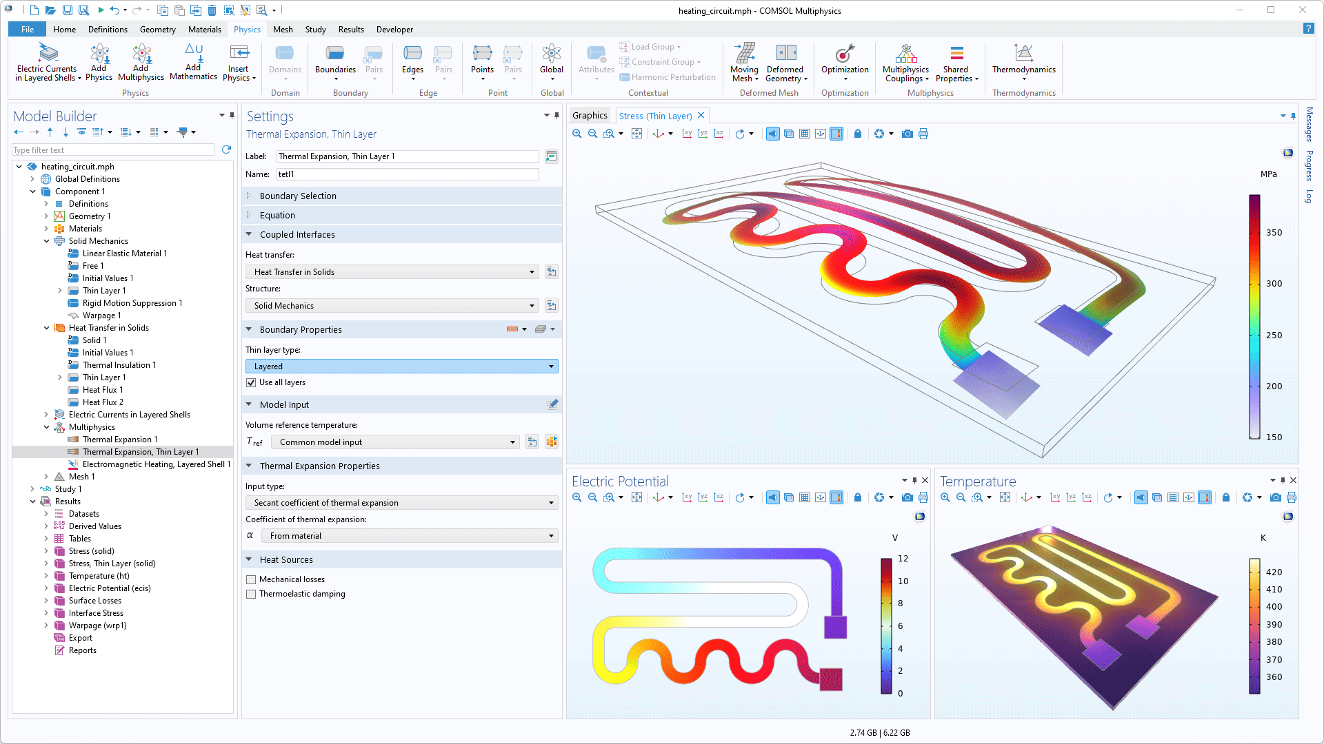
Thermal Expansion, Thin Layer Multiphysics Coupling
The new Thermal Expansion, Thin Layer multiphysics coupling node enables the thermal expansion in boundaries that have a Thin Layer material model to be coupled with the temperature field on the same boundaries computed in a Heat Transfer interface.
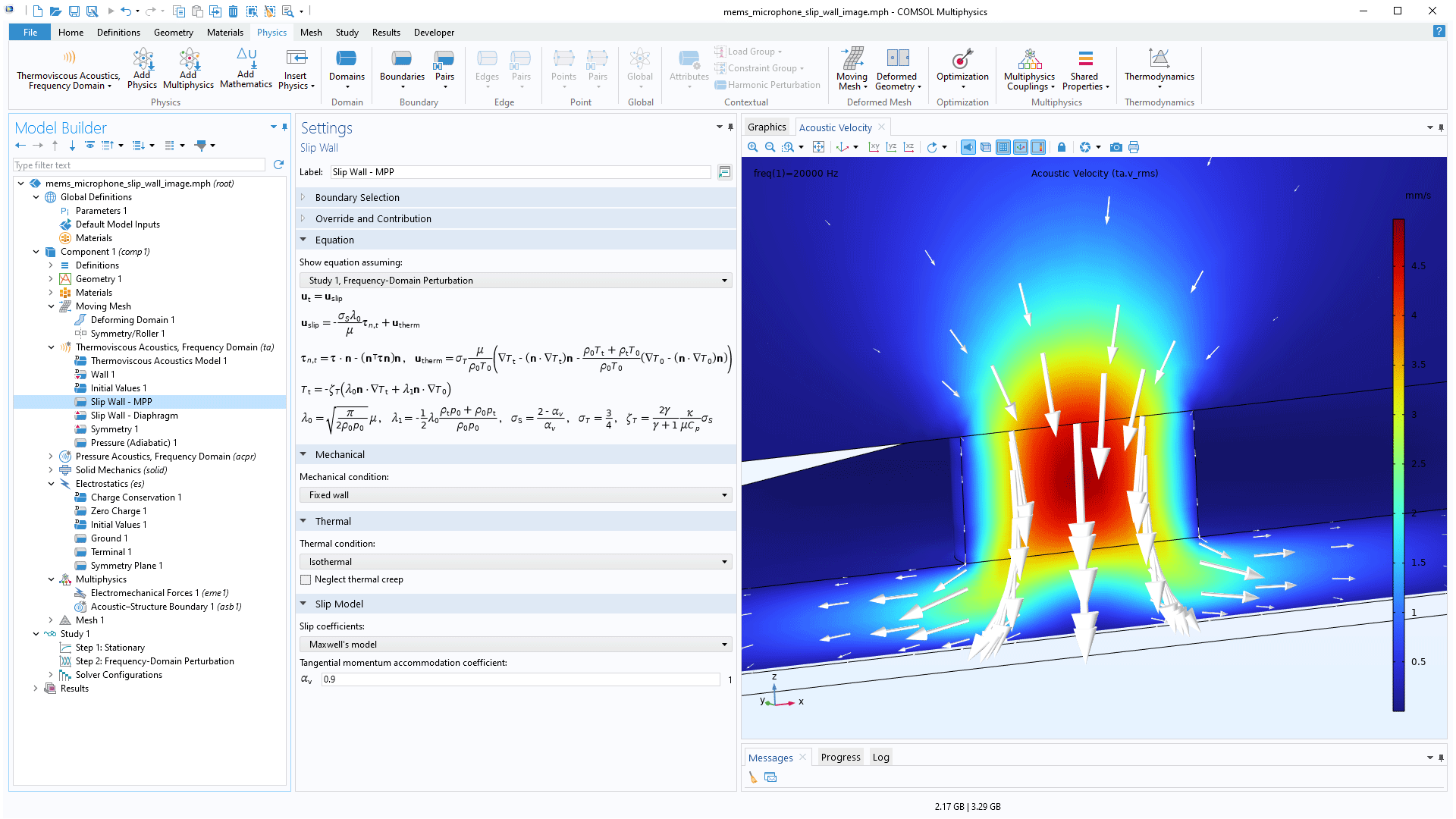
Slip Wall Boundary Condition
A new Slip Wall boundary condition can be used to model the effective nonideal wall conditions that exist in the slip flow regime, provided that the Knudsen number is in the range from 0.001 to 0.1. This feature is used for systems with very small geometrical dimensions or systems running at very low ambient pressures. This is relevant when modeling, for example, MEMS transducers and other microdevices. To model a slip wall on an interior boundary, the Interior Slip Wall feature is available. Note that these features require the Acoustics Module.
Unconstrained Structures when Modeling Contact
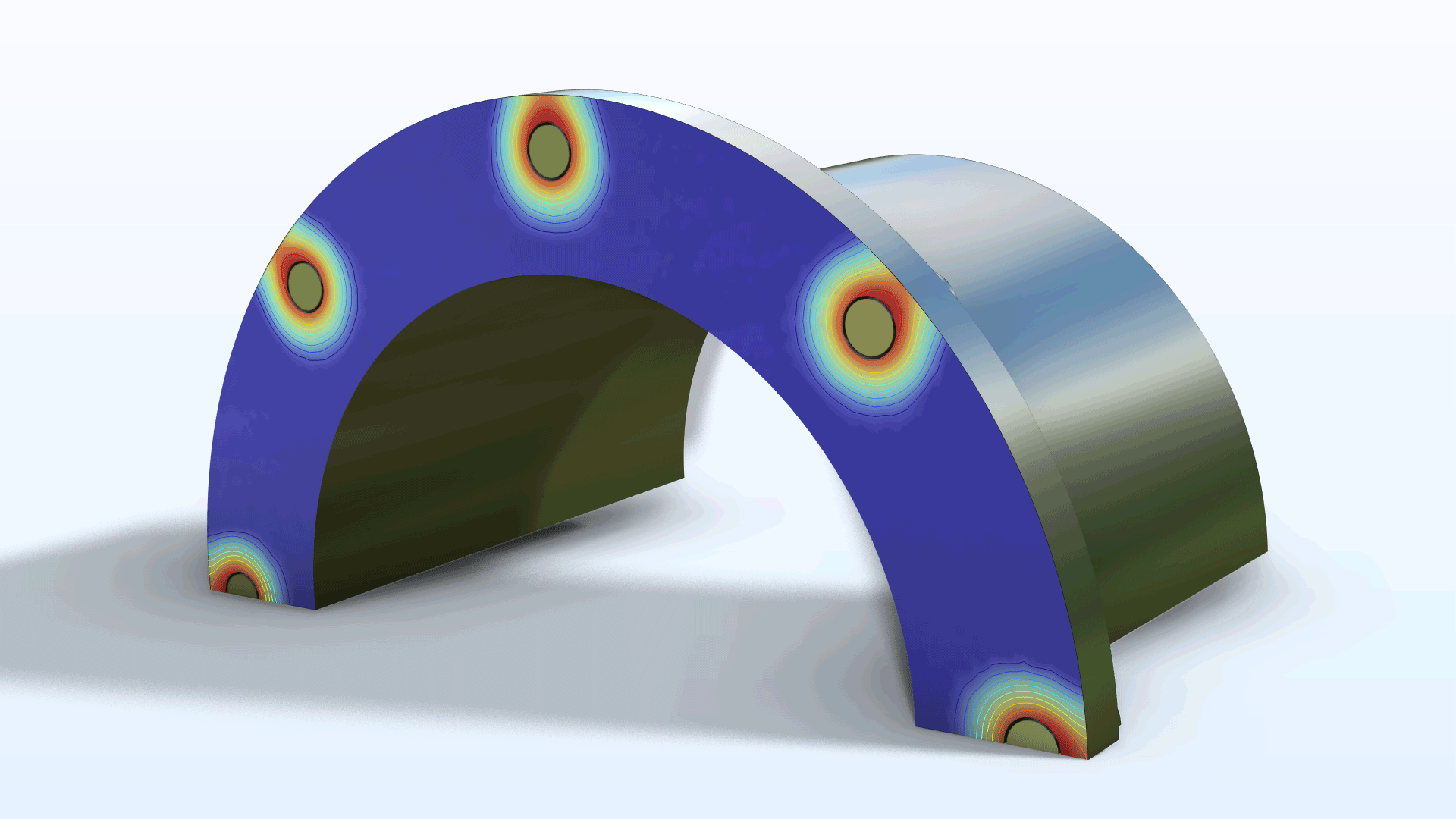
Contact problems often involve insufficient constraints until contact has been established. As a result, the stiffness matrix becomes singular. A new Stabilization feature has been added to alleviate this inherent difficulty.
Limited Displacement
The possibility to prescribe a limited displacement (that is, the maximum distance that a point, edge, or boundary can move in a certain direction) has been added to the Solid Mechanics, Multibody Dynamics, Shell, Layered Shell, and Membrane interfaces. This functionality can be viewed as a simplified version of contact analysis, where no second object is needed to stop the movement. In previous versions, this functionality was only available in the edge-type interfaces, such as Beam or Truss, and therefore was only applicable to edges or points.
New Phase Field in Solids Interface
Phase-field modeling can be used for numerous physics applications, and a new Phase Field in Solids interface has been introduced in this version. This is a specialized interface for the modeling of phenomena involving moving interfaces within solids, such as the propagation of cracks, damage evolution, and the growth of grain boundaries.
New Transport in Solids Interface
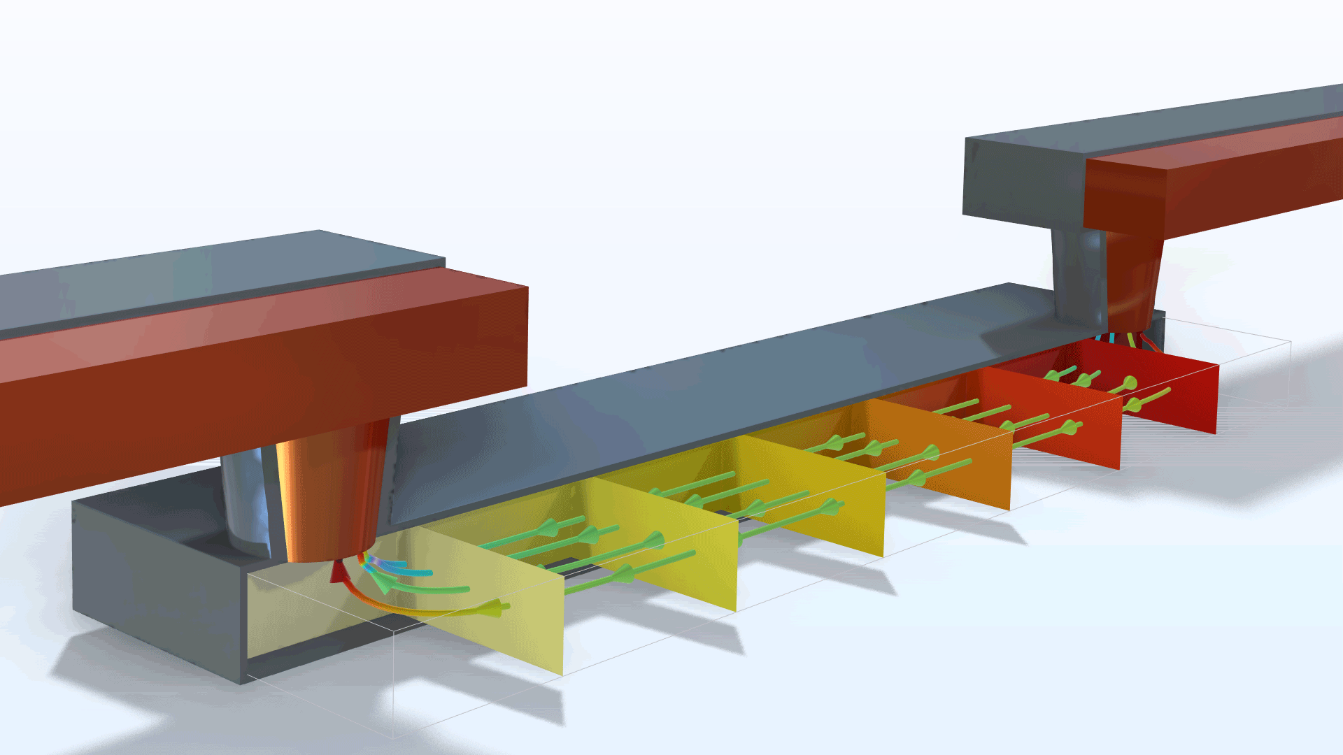
A new Transport in Solids interface has been added for modeling transport of species, electromigration, hydrogen embrittlement, and other transport phenomena in solid materials. The interface allows for stationary and time-dependent studies of transport involving one or several species. In addition, if the diffusion problem is stress driven, the Transport in Solids interface can be coupled with a Solid Mechanics interface.
New Tutorial Models
COMSOL Multiphysics® version 6.2 brings several new tutorial models to the MEMS Module.
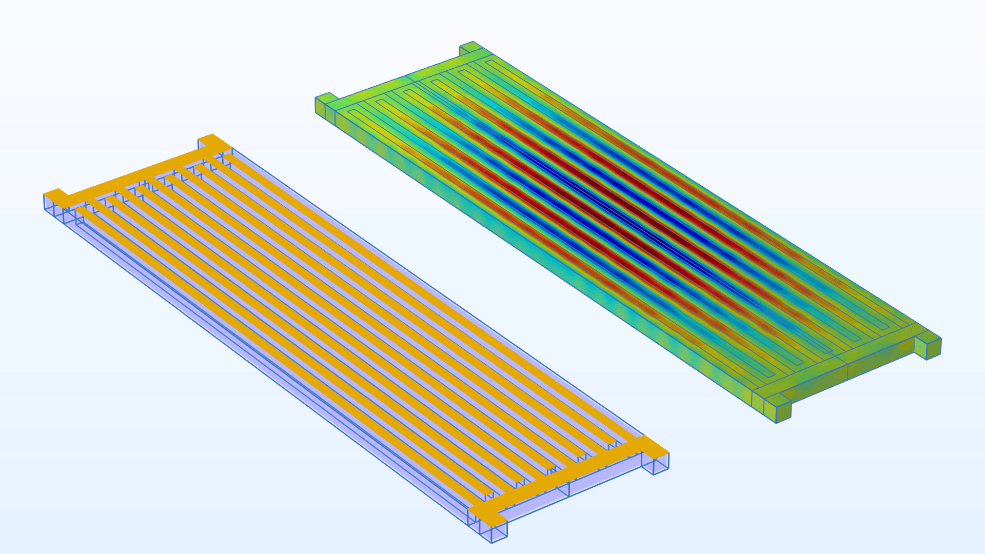
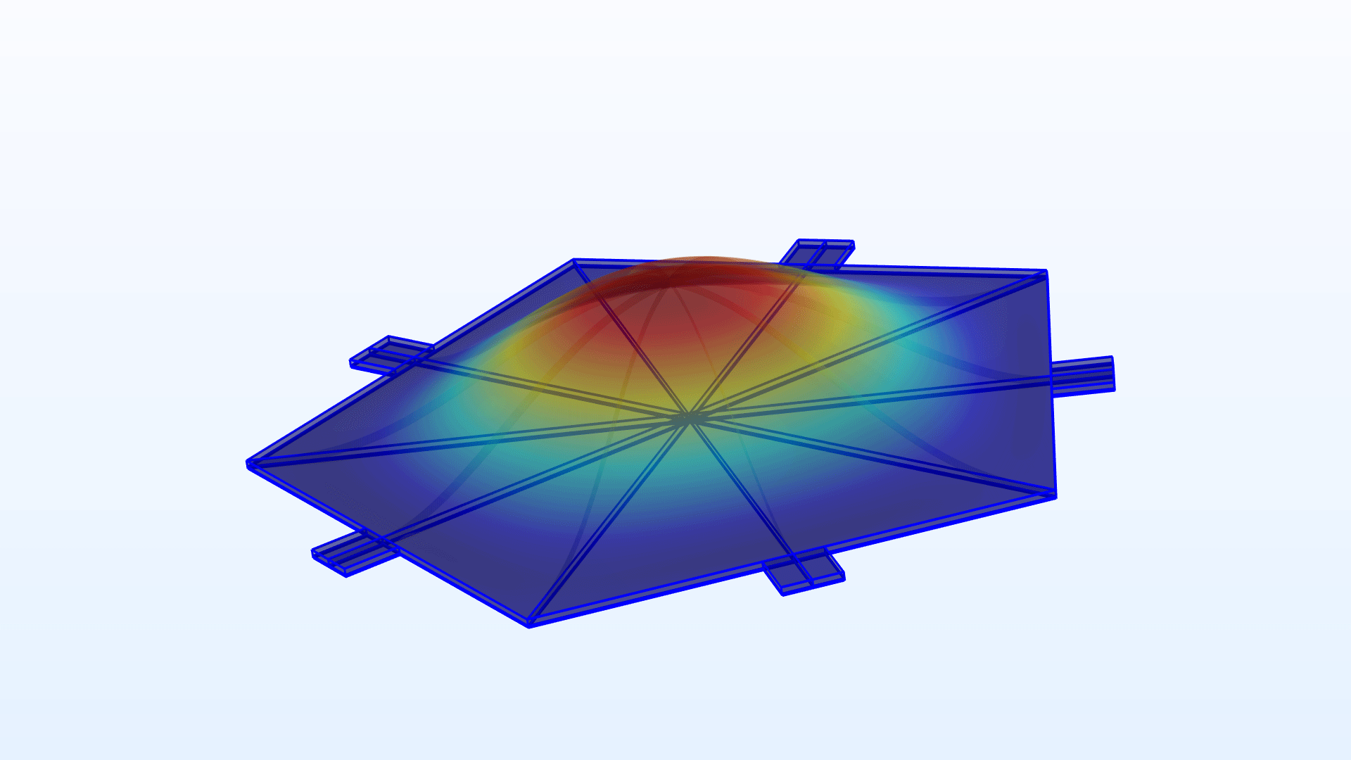
Aluminum Nitride Lamb Wave Resonator — 3D
Application Library Title:
aln_lamb_wave_resonator_3d
Download from the Application Gallery
Capacitive Micromachined Ultrasonic Transducer with Lumped Model
Application Library Title:
capacitive_micromachined_ultrasonic_transducer_lumped_model
Download from the Application Gallery
Solidly Mounted Resonator 2D with Uncertainty Quantification*
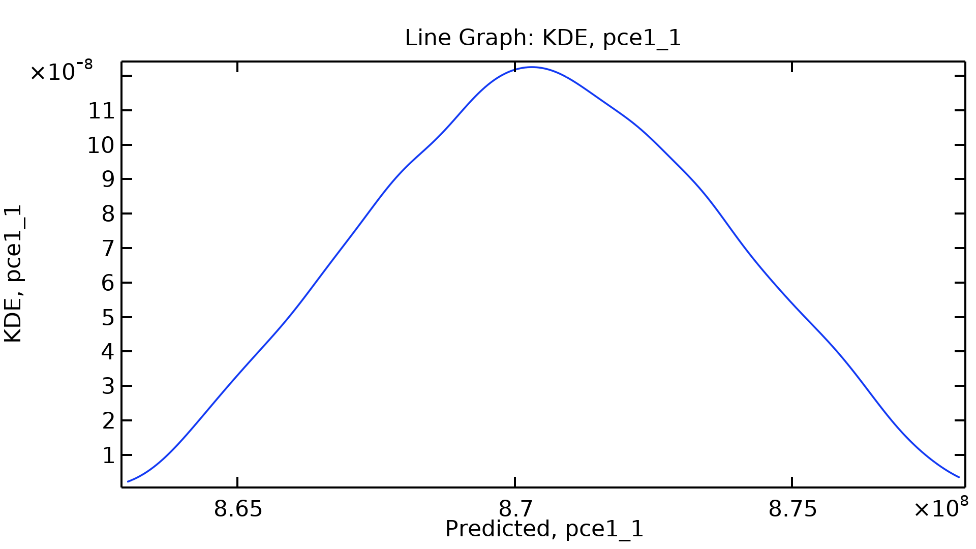
Application Library Title:
solidly_mounted_resonator_2d_uncertainty_quantification
Download from the Application Gallery
*Requires the Uncertainty Quantification Module
Thin-Film BAW Resonator with Equivalent Circuit
Application Library Title:
thin_film_baw_resonator_3d_equivalent_circuit
Download from the Application Gallery